
Air admittance valve

Active Publication Date: 2021-10-14
OATEY CO
View PDF0 Cites 0 Cited by
  • Summary
  • Abstract
  • Description
  • Claims
  • Application Information

AI Technical Summary

Benefits of technology

The present invention relates to an air admittance valve and a one-way valve for selectively venting ambient air into a plumbing drain and waste system. The valves have a flexible sealing member with a support ring that seals against a valve seat and can open or close a boundary between an inlet and an outlet. The valves are designed to prevent discharge from the closed system into the ambient air and to ensure proper sealing even in the event of lateral displacement of the sealing member. The valves have a unique design that allows for translation and angulation of the sealing member within the interior of a cap and ensures a tight airtight seal.

Problems solved by technology

The carrier structure according to these exemplary disclosures has had certain drawbacks in commercial implementations of the air admittance valve, including the risk of increased frictional resistance between the carrier structure and the guiding means on the valve cap.
Because the carrier structures of such disclosures, as well as similar mechanical structures in other known air admittance valve patent references, are configured to mechanically translate along the means of the cap, these parts are constantly subjected to frictional forces and other mechanical wear.
Over time, these sliding surfaces may become worn, roughened, and may generate frictional resistance that would cause the tension sealing membrane to fail to open or close under normal operating pressure differentials.
Because air admittance valves need to operate under a specific range of pressure differentials and must remain sensitive to slight changes in pressure, this drawback could result in failure of the air admittance valve to operate as intended.

Method used


Image

  • Air admittance valve
  • Air admittance valve
  • Air admittance valve

Examples


Embodiment Construction

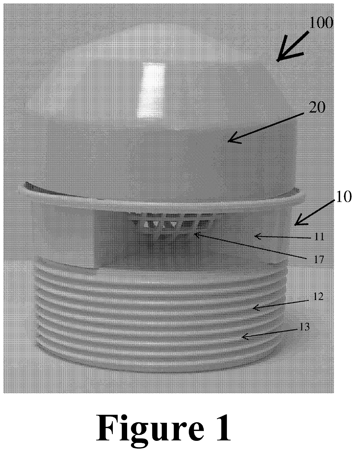
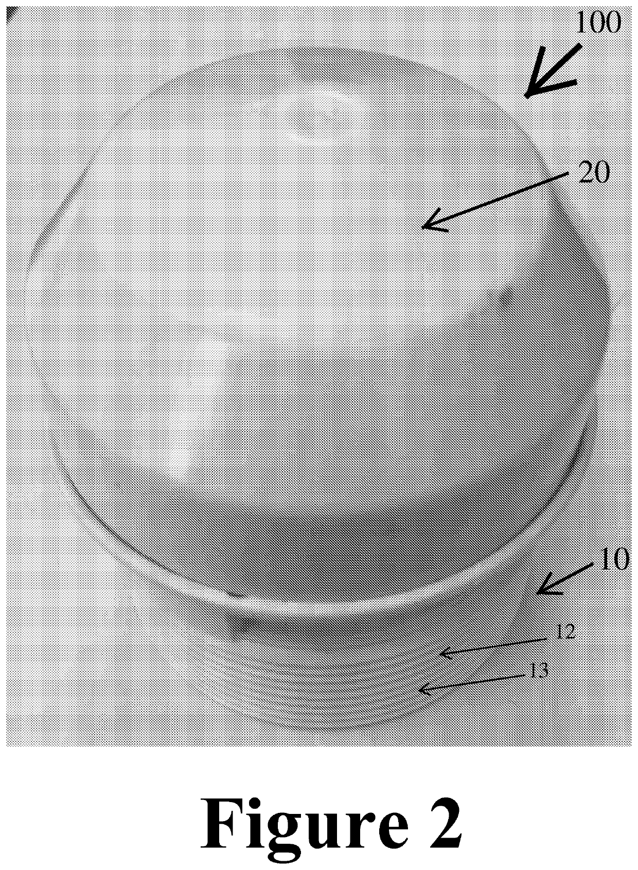
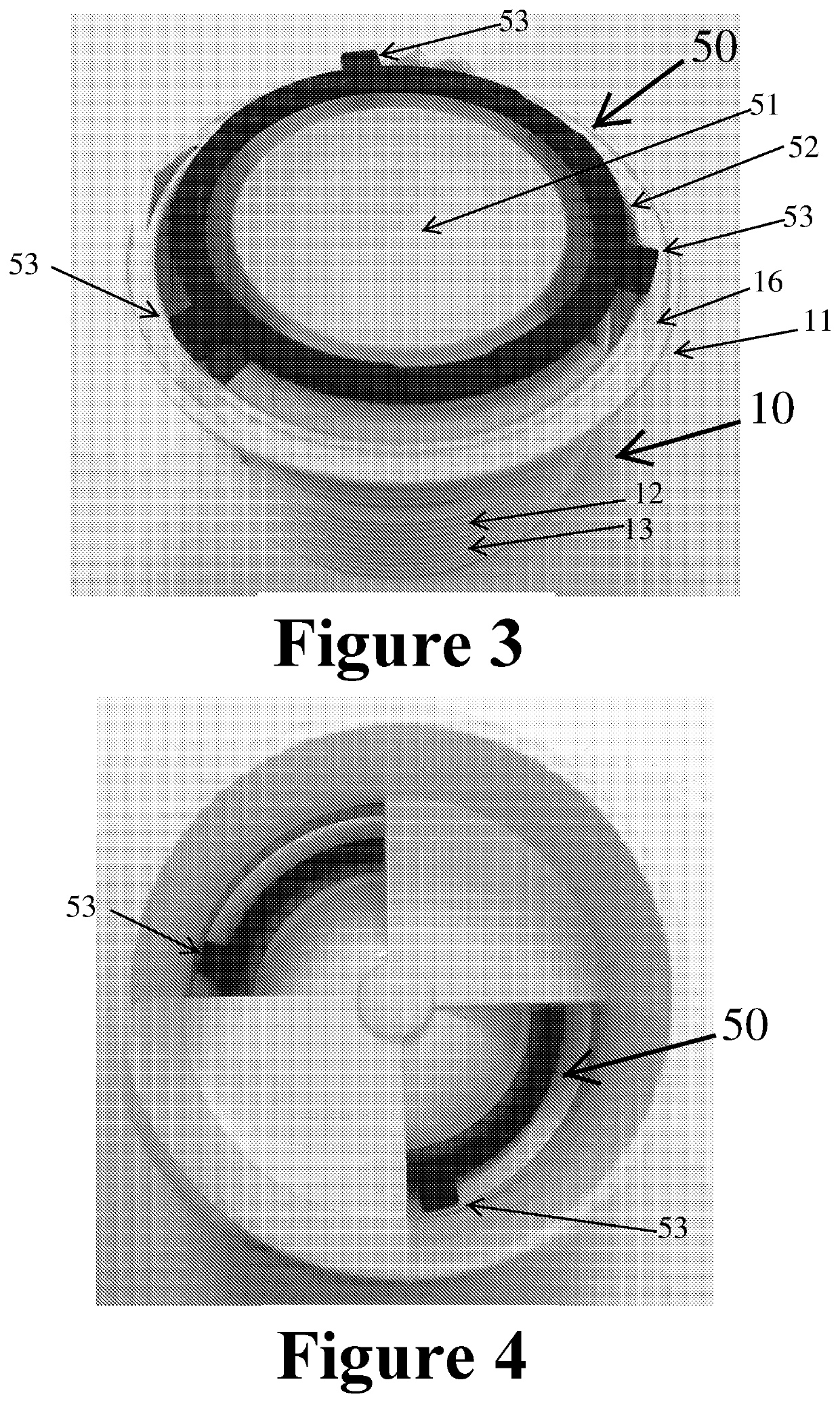
strate a fully assembled configuration of an air admittance valve 100 (or one way valve) in accordance with an embodiment of the invention. The air admittance valve 100 comprises a valve body 10, a cap member 20 mounted thereon, and a sealing member 50 (see FIGS. 3-5 and 10-11). The valve body 10 may generally be divided into a top portion 11 and a bottom portion 12. The bottom portion 12 of the valve body 10, as shown, includes a connecting portion which may be connected to a closed system, such as a plumbing system, by way of a set of externally disposed threads 13 on an outer portion of the bottom portion 12. The threaded outer portion 13 is provided to permit the air admittance valve to be secured to an internally threaded conduit or pipe (not shown), for example, or to an adapter structure connected to the top of a vent pipe. The pipe threads are preferably NPT threads (National Pipe Threads). Although threads 13 are illustrated, it will be understood that alternative connectiv...


PUM


Abstract

The present invention relates to an air admittance valve (AAV) that operates automatically at low pressures to selectively open and close an air passageway between an inlet and an outlet. The AAV comprises a valve body having a centrally disposed, internal valve chamber in communication with the ambient environment, and having a valve seat. The AAV includes a sealing member having a flexible diaphragm that is fastened to a support ring, the ring defining one or more lugs on an outer periphery thereof. The AAV further includes a cap member within which the sealing member may be disposed, such that the one or more lugs may interact with an interior surface of the cap. The sealing member may selectively seal or unseal from the valve seat in response to pressure differentials between the inlet and the outlet.

Description

CROSS-REFERENCE TO RELATED APPLICATIONS[0001]The present application claims priority to U.S. Provisional Patent Application No. 62 / 374,494, filed Aug. 12, 2016. The contents of that application are hereby incorporated in their entirety by reference.TECHNICAL FIELD[0002]The present disclosure relates to an air admittance valve for providing automatic, low pressure, one-way venting into a closed system, such as a plumbing drain and waste system.BACKGROUND[0003]Air admittance valves are frequently used in a variety of plumbing applications to seal unwanted gases from escaping a plumbing system, but to also allow ambient air into the plumbing system to prevent negative pressure or a vacuum within the system. Thus, air admittance valves function as a one-way valve that seals at zero pressure and against higher, positive pressure airflow in a first direction (i.e., out of the plumbing system) but which unseals to allow lower pressure airflow in a second direction substantially opposite th...

Claims


Application Information

Patent Timeline
IPC IPC(8): E03F5/08E03F1/00F16K15/02
CPCE03F5/08F16K15/023E03F1/006F16K24/06E03D9/04E03B11/08F16L55/07
Inventor LORKOWSKI, AARONBROWN, KENNETHZHANG, KAI
Owner OATEY CO
Learn More