Eureka AIR delivers breakthrough ideas for toughest innovation challenges, trusted by R&D personnel around the world.

Method of preventing battery discharge and electronic control unit performing the same

Active Publication Date: 2019-10-17
HYUNDAI AUTOEVER
View PDF0 Cites 1 Cited by
  • Summary
  • Abstract
  • Description
  • Claims
  • Application Information

AI Technical Summary

Benefits of technology

The present invention proposes a method for preventing the battery in a vehicle from becoming discharged due to low voltage levels after vehicle functions have been turned off. This method involves detecting the voltage of the battery, and when a low voltage level is detected, transmitting a signal to multiple controllers to enter a low power mode to minimize battery drain. The method aims to prevent damage to the battery caused by battery discharging, and to ensure the optimal performance of the vehicle's functions.

Problems solved by technology

The amount of power that may be supplied by only the battery for vehicle is limited because the battery for vehicle has a limited charge capacity.
However, when a problem occurs in a specific controller, the specific controller continues to transmit a network management message to the vehicle.
Accordingly, there is a problem in that the battery is discharged because all the controllers do not enter the low power mode.

Method used


Image

  • Method of preventing battery discharge and electronic control unit performing the same
  • Method of preventing battery discharge and electronic control unit performing the same
  • Method of preventing battery discharge and electronic control unit performing the same

Examples


first embodiment

[0039]Furthermore, in the following description, the elements included in the electronic control unit 10 according to the present invention are individually described, but this is only one embodiment of the elements, and any one element and the other element may be implemented in a merged form.

[0040]The electronic control unit 10 may be mounted on a vehicle as an independent part, but may be implemented as one element or function of an electronic control unit (ECU) mounted on a vehicle.

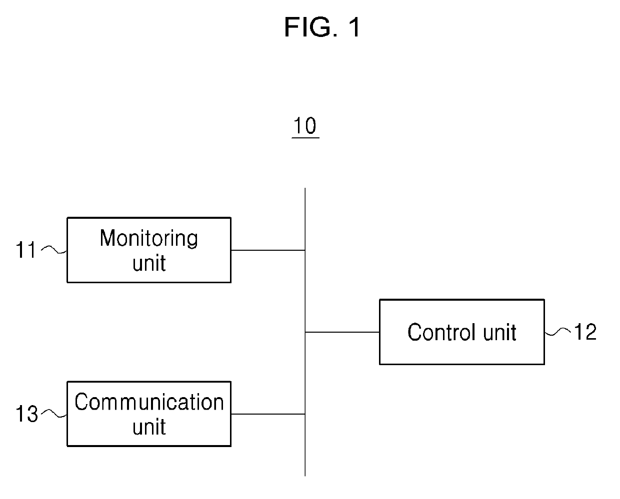
[0041]Referring to FIG. 1, the electronic control unit 10 may include a monitoring unit 11, a control unit 12 and a communication unit 13, and may further include other additional elements necessary to achieve an object of the present invention.

[0042]The monitoring unit 11 may monitor at least one of a voltage of the battery (B+, BATTERY PLUS IGN KEY) 50 connected to the outside of the electronic control unit 10 and vehicle function power (IGN). For example, the monitoring unit 11 may monitor operatin...

third embodiment

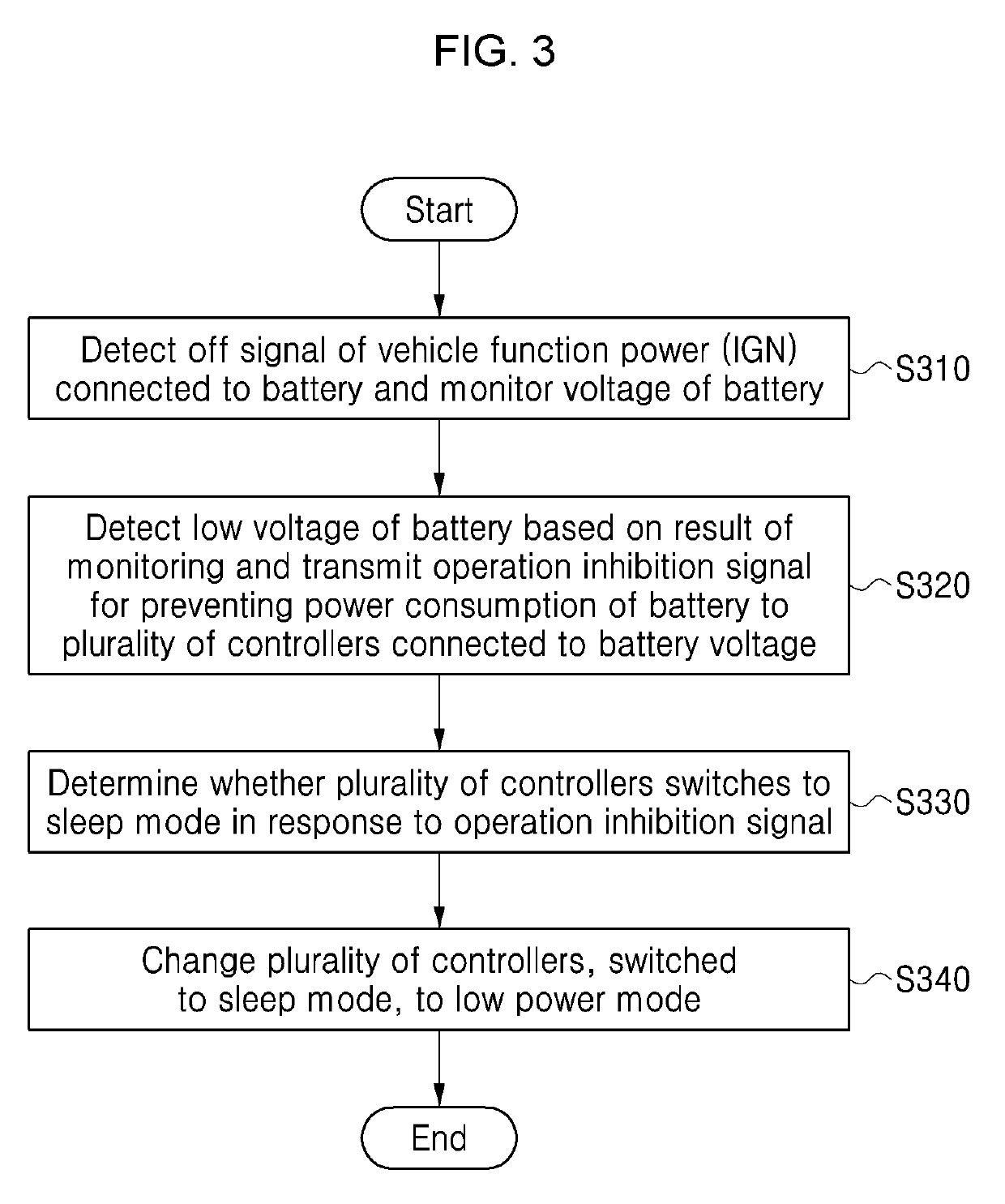
[0057]FIG. 3 is a flowchart showing a method of preventing the discharge of a battery according to the present invention.

[0058]The method is only one embodiment for achieving an object of the present invention. Some steps may be deleted from or added to the method or any one step may be included in another step, if necessary.

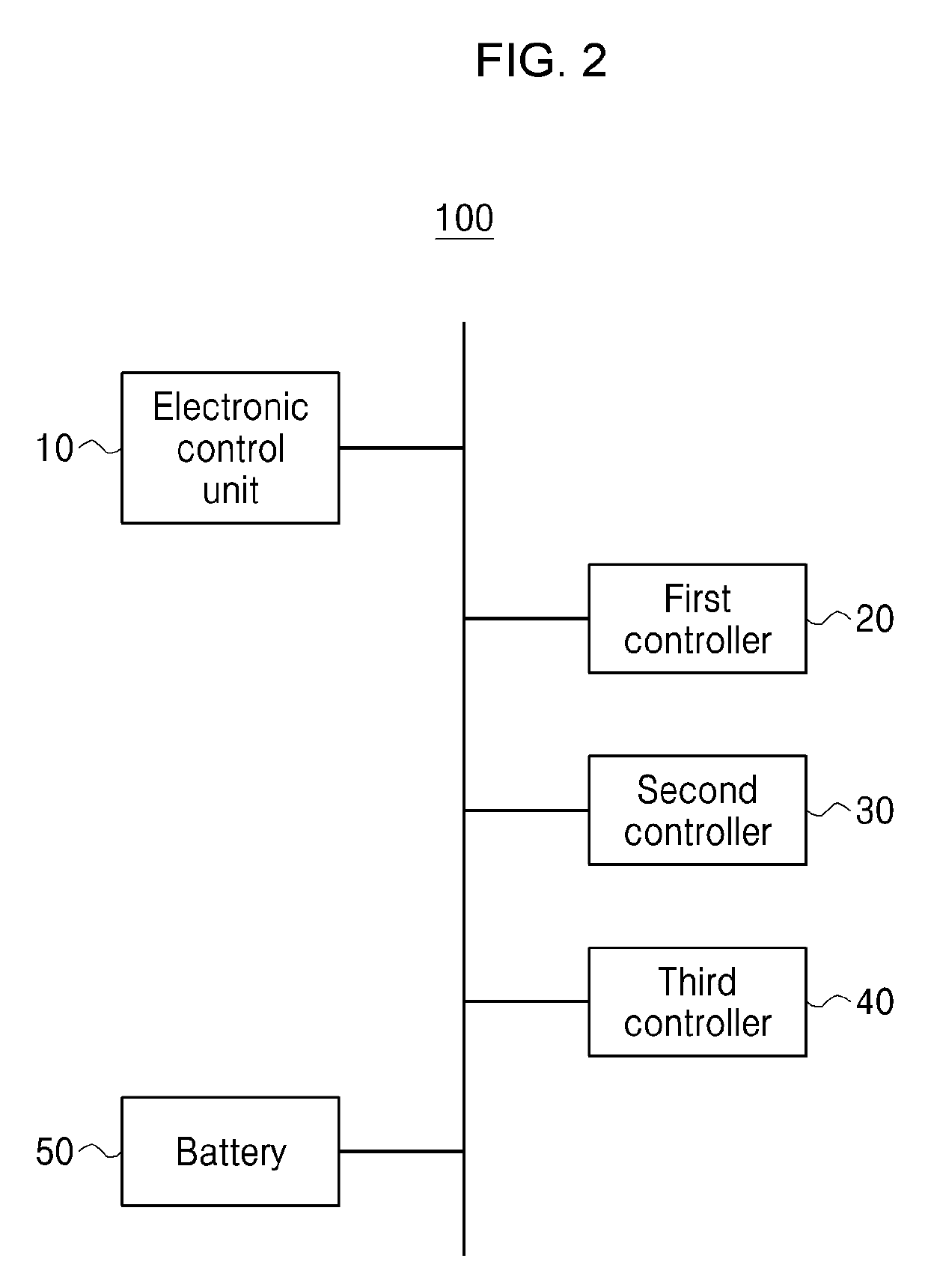
[0059]Referring to FIG. 3, the monitoring unit 11 detects the off signal of the vehicle function power (IGN) connected to the battery 50, and monitors a voltage of the battery 50 connected to the first controller 20, the second controller 30 and the third controller 40 (S310).

[0060]As described above, when the vehicle function power (IGN) is off, the first controller 20, the second controller 30 and the third controller 40 perform respective operations using power of the battery 50 and must switch to the sleep mode at the same time. When an error occurs in a controller, all the first controller 20, the second controller 30 and the third controller 40 fail in swi...

second embodiment

[0069]FIG. 4 is a detailed flowchart illustrating step S330 of FIG. 3. FIG. 5 is a diagram showing the state in which controllers are controlled by the battery discharge prevention system 100 according to the present invention.

[0070]Referring to FIG. 4, first, the control unit 12 determines whether all the plurality of controllers switch to the sleep mode in response to the operation inhibition signal (S330-1).

[0071]If it is determined that all the first controller 20, the second controller 30 and the third controller 40 have not switched to the sleep mode, the control unit 12 transmits a wakeup deactivation signal to a specific controller (e.g., second controller) that has not switched to the sleep mode (S330-2, NO). If it is determined that all the first controller 20, the second controller 30 and the third controller 40 have switched to the sleep mode, the control unit 12 performs step S340 of FIG. 3.

[0072]The remaining controllers (e.g., first controller and third controller) ex...


PUM


Abstract

Disclosed is a method for an electronic control unit to prevent the discharge of a battery. The method includes the steps of detecting an off signal of vehicle function power connected to a battery and monitoring a voltage of the battery, detecting a low voltage of the battery based on a result of the monitoring and transmitting an operation inhibition signal for preventing power consumption of the battery to a plurality of controllers, and determining whether the plurality of controllers switch to a sleep mode in response to the operation inhibition signal.

Description

CROSS REFERENCE TO RELATED APPLICATION[0001]This application is based on and claims priority under 35 U.S.C. 119 to Korean Patent Application No. 10-2018-0042750, filed on Apr. 12, 2018, in the Korean Intellectual Property Office, the disclosures of which is herein incorporated by reference in their entireties.BACKGROUND OF THE INVENTION1. Technical Field[0002]The present invention relates to an electronic control unit and a method of preventing the discharge of a battery and, more particularly, to a method and electronic control unit for preventing the discharge of a battery attributable to an error of controllers after the off of vehicle function power.2. Description of the Related Art[0003]In general, a power source mounted on a vehicle is configured with battery power and generator power. The battery power is used to drive a startup motor when the vehicle is initially driven or used when an engine is stopped.[0004]The amount of power that may be supplied by only the battery for ...

Claims


Application Information

Patent Timeline
IPC IPC(8): H02J7/00G01R31/3835
CPCH02J7/0031H02J2007/0067H02J7/0063G01R31/3835H02J7/0029H02J7/00306H02J2310/46Y02T10/92H02J7/007182H02J7/0032B60R16/033H02J7/0025
Inventor KIM, KYOUNG TAE
Owner HYUNDAI AUTOEVER
Why Eureka
Eureka Blog
Learn More