Eureka AIR delivers breakthrough ideas for toughest innovation challenges, trusted by R&D personnel around the world.

Droplet discharging head and droplet discharging apparatus

Inactive Publication Date: 2007-09-20
SEIKO EPSON CORP
View PDF1 Cites 0 Cited by
  • Summary
  • Abstract
  • Description
  • Claims
  • Application Information

AI Technical Summary

Benefits of technology

[0006]An advantage of the invention is to provide a droplet discharging head and a droplet discharging apparatus that are each constructed so as to detect whether or not foreign matters are attached on the discharging ports or the like and that each improve the accuracy of discharging of droplets, for example, by preventing the flight deflection of the discharged droplets.
[0007]A droplet discharging head according to a first aspect of the invention includes a first drive unit and a base coupled to the first drive unit. The base includes a portion defining a first cavity, a portion defining a first discharging port, and a portion defining a first through hole through which the portion defining a first cavity and the portion defining a first discharging port communicate with each other. The droplet discharging head also includes a plurality of first electrode branches and a plurality of second electrode branches. The plurality of first electrode branches and the plurality of second electrode branches are disposed alternately apart from each other on a periphery of the portion defining a first discharging port, and extend on a surface of the portion defining a first through hole.
[0008]When these features are used, it is possible to check whether or not foreign matters are attached on the periphery of the portion defining a first discharging port or on the surface of the portion defining a first through hole by measuring a resistance between the first electrode branches and second electrode branches. As a result, it is possible to improve the accuracy of discharging of droplets from the droplet discharging head. Providing the plurality of first electrode branches and the plurality of second electrode branches as well as forming those electrode branches closely on the periphery of the portion defining a first discharging port or on the surface of the portion defining a first through hole allows the accuracy of detection of attached foreign matters to be improved.
[0009]A droplet discharging head according to a second aspect of the invention includes a first drive unit, a second drive unit, and a base coupled to the first and second drive units. The base includes a portion defining a first cavity controlled by the first drive unit, a portion defining a first discharging port, a portion defining a first through hole through which the portion defining a first cavity and the portion defining a first discharging port communicate with each other, a portion defining a second cavity controlled by the second drive unit, a portion defining a second discharging port, and a portion defining a second through hole through which the portion defining a second cavity and the portion defining a second discharging port communicate with each other. The droplet discharging head also includes a first electrode formed on a periphery of the portion defining a first discharging port, a second electrode formed on a periphery of the portion defining a first discharging port, a third electrode formed on a periphery of the portion defining a second discharging port, and a fourth electrode formed on a periphery of the portion defining a second discharging port. The first to fourth electrodes are formed apart from each other.
[0010]When these features are used, it is possible to check whether or not foreign matters are attached on the periphery of the portion defining a first discharging port or the like by measuring a resistance between the first and second electrodes. As a result, it is possible to improve the accuracy of discharging of droplets from the droplet discharging head. Additionally it is possible to measure a resistance at a plurality of portions defining a discharging port separately. This makes it possible to halt discharging of droplets from a portion defining a discharging port where attachment of a foreign matter has been confirmed, allowing the maintenance frequency of the head to be reduced.
[0011]A droplet discharging head according to a third aspect of the invention includes a first drive unit and a base coupled to the first drive unit. The base includes a portion defining a first cavity, a portion defining a first discharging port, and a portion defining a first through hole through which the portion defining a first cavity and the portion defining a first discharging port communicate with each other. The droplet discharging head also includes a first electrode and a second electrode. The first and second electrodes are formed apart from each other on a periphery of the portion defining a first discharging port.

Problems solved by technology

This may cause some discharging ports to become clogged, preventing normal discharging of droplets.
Clogging in the discharging ports causes problems, such as occurrence of missing dots in a printed image.
However, while the technology disclosed in the related art example described above is suited to determining whether or not it is completely impossible to discharge droplets through the discharging ports, it is not suited to determining whether or not foreign matters, such as ink ingredients, are attached on the peripheries of the discharging ports.
In other words, the technology is not sufficient to prevent the flight deflection of droplets caused by the foreign matters attached.

Method used


Image

  • Droplet discharging head and droplet discharging apparatus
  • Droplet discharging head and droplet discharging apparatus
  • Droplet discharging head and droplet discharging apparatus

Examples


Embodiment Construction

[0040]Embodiments of a droplet discharging head and a droplet discharging apparatus (film forming apparatus) according to the invention will now be described. First, a droplet discharging apparatus according to the invention, that is, a droplet discharging apparatus including a droplet discharging head according to the invention will be described before explaining the droplet discharging head according to the invention.

Droplet Discharging Apparatus

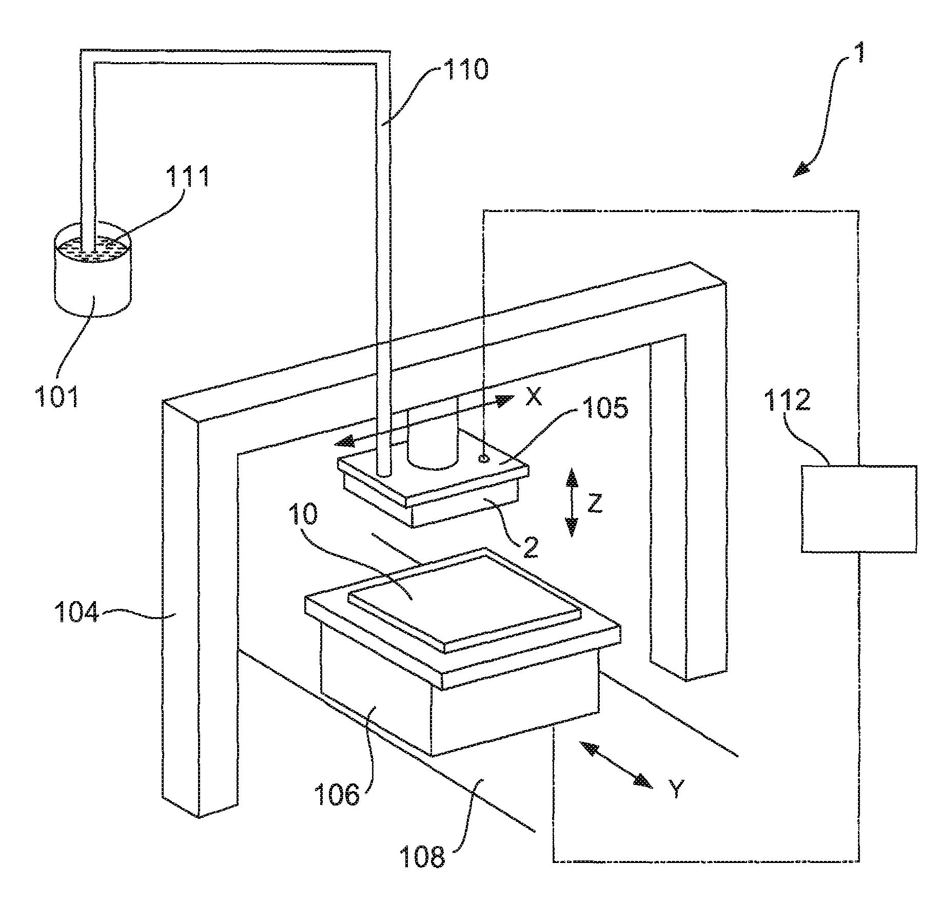
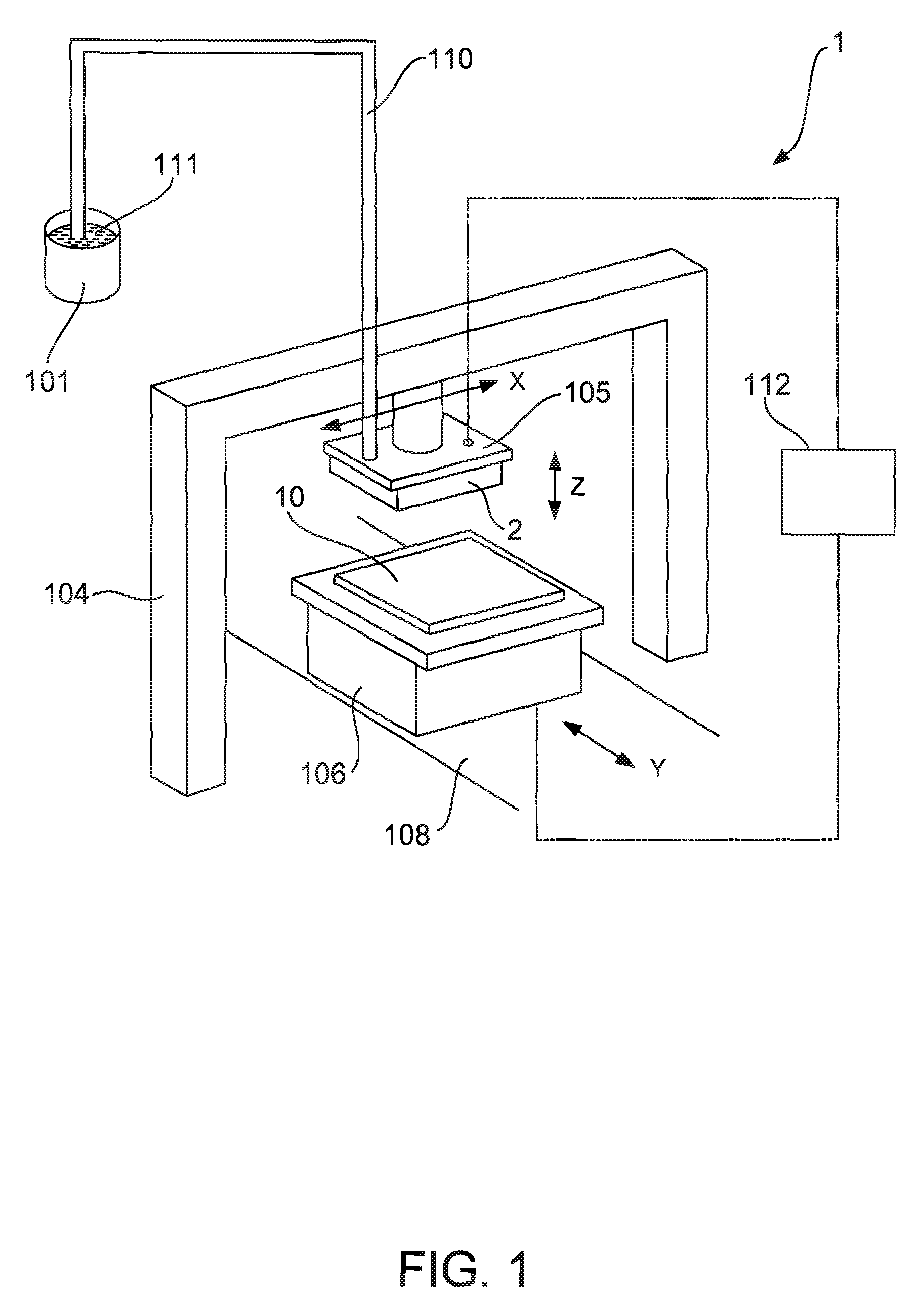
[0041]FIG. 1 is a drawing schematically showing construction of a droplet discharging apparatus according to one embodiment. As shown in FIG. 1, a droplet discharging apparatus 1 includes a carriage 105 that includes a plurality of droplet discharging heads 2 for discharging droplets, a carriage moving mechanism (moving means) 104 that moves the carriage 105 in one horizontal direction (hereinafter referred to as “X axis direction”), a stage 106 that holds a substrate 10 to which droplets are given, a stage moving mechanism (moving means) ...


PUM


Abstract

A droplet discharging head includes a first drive unit and a base coupled to the first drive unit. The base includes a portion defining a first cavity, a portion defining a first discharging port, and a portion defining a first through hole through which the portion defining a first cavity and the portion defining a first discharging port communicate with each other. The droplet discharging head also includes a plurality of first electrode branches and a plurality of second electrode branches. The plurality of first electrode branches and the plurality of second electrode branches are disposed alternately apart from each other on a periphery of the portion defining a first discharging port, and extend on a surface of the portion defining a first through hole.

Description

1. TECHNICAL FIELD[0001]Several aspects of the present invention relate to a droplet discharging head and a droplet discharging apparatus.2. RELATED ART[0002]In recent years, as droplet discharging apparatuses using inkjet technology, image forming apparatuses, such as ink jet printers, used to print images on paper, have been developed as well as film forming apparatuses used to form metal wires for a display panel.[0003]For example, a droplet discharging head (ink jet head) for such an ink jet printer, which has a plurality of discharging ports (nozzle opening), causes ink ingredients to be deposited and attached on peripheries of the discharging ports. This may cause some discharging ports to become clogged, preventing normal discharging of droplets. Clogging in the discharging ports causes problems, such as occurrence of missing dots in a printed image.[0004]According to a related art example to address those problems, JP-A-8-323993, it is possible to detect non-discharging of d...

Claims


Application Information

Patent Timeline
IPC IPC(8): B41J2/06G01D11/00
CPCB41J2/14072B41J2/01B41J2/17
Inventor TAKAHASHI, HAYATOSAKAI, SHINRI
Owner SEIKO EPSON CORP
Why Eureka
Eureka Blog
Learn More