Reversal mechanism

Active Publication Date: 2019-04-04
SUPERBA SAS
View PDF3 Cites 1 Cited by
  • Summary
  • Abstract
  • Description
  • Claims
  • Application Information

AI Technical Summary

Benefits of technology

[0005]The aim of the present invention is to address these issues by proposing a mechanism which, on one hand, makes it possible to a

Problems solved by technology

However, the disadvantage of slowing down the conveyor belt's movement speed is that it slows the wire bundle

Method used


Image

  • Reversal mechanism

Examples


Example

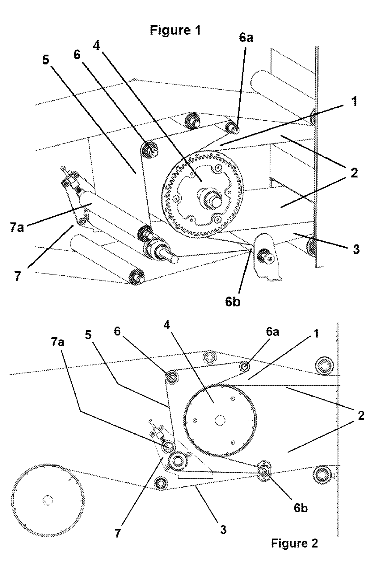
[0011]The present invention focuses on a reversal mechanism 1 of a product placed between a first upper conveyor belt 2 and a second lower conveyor belt 3. The first conveyor belt 2 is linked to at least one cylinder 4 on one end, characterized in that the reversal mechanism 1 contains at least one means for clamping the product placed against the first conveyor belt 2 moving on a portion of the periphery of the cylinder 4.

[0012]The reversal mechanism 1 of the invention makes it possible to stack several conveyor belts 2, 3 inside a treatment device, particularly wire heat treatment. The reversal mechanism 1 makes it possible to transfer a product between the first upper belt 2 and the second lower belt 3 while retaining the layout and arrangement similar to that of the conveyor belt 2 to the other 3. This transfer quality is obtained through the product's clamping means, which presses the product against the upper conveyor belt 2 while moving on the cylinder 4. This pressure of the...


PUM

PropertyMeasurementUnit
Fractionaaaaaaaaaa
Forceaaaaaaaaaa
Pressureaaaaaaaaaa

Abstract

The present invention is a mechanism that reverses a product placed between a first upper conveyor belt and a second lower conveyor belt. The first one is linked to at least one cylinder on one end, characterized in that the reversal mechanism contains at least one means for clamping the product placed against the first conveyor belt moving on a portion of the periphery of the cylinder.

Description

CROSS-REFERENCE TO RELATED APPLICATION[0001]This application claims priority from European Patent Application No. 17306328.0 filed Oct. 4, 2017, the contents of which are hereby incorporated by reference into this application.FIELD OF THE INVENTION[0002]The present invention relates to the area of a wire management mechanism in a wire heat treatment device and, more particularly, in the area of the management of wire routing inside a heat treatment device.BACKGROUND OF THE INVENTION[0003]The common method to treat a wire bundle, particularly by heat or steam treatment, is to run the wire bundle through a drying oven. Traditionally, this operation is done by placing a wire bundle on a conveyor belt that crosses one or more drying ovens. How long the wire bundle must undergo this treatment depends, partly, on the length of the conveyor belt moving in the drying oven as well as how quickly the said conveyor belt is moving.[0004]To treat the bundle longer, it becomes necessary to increa...

Claims


Application Information

Patent Timeline
IPC IPC(8): B65G47/252B65G15/14B65G43/08B65G23/44
CPCB65G47/252B65G15/14B65G43/08B65G23/44D06B17/00D06B17/005D06B23/04D02J13/001
Inventor LIEBMANN, HUBERTMASSOTTE, PHILIPPE
Owner SUPERBA SAS
Why Eureka
Try Eureka