Rolling guide device

Active Publication Date: 2019-04-11
THK CO LTD
View PDF0 Cites 0 Cited by
  • Summary
  • Abstract
  • Description
  • Claims
  • Application Information

AI Technical Summary

Benefits of technology

[0011]According to the present invention, in a case in which the maximum clearance “t” between the both end portions of the holding belt which are opposed to each other in the endless circulation path is smaller than the amount δ defined by the expression described above, even when the holding belt in the no-load path is pulled due to rolling of the rolling elements in the load path, a leading end of

Problems solved by technology

Therefore, when a relative motion occurs between the track rail and the moving block, th

Method used


Image

  • Rolling guide device
  • Rolling guide device
  • Rolling guide device

Examples


Example

[0019]Now, detailed description is made of a rolling guide device according to one embodiment of the present invention with reference to the accompanying drawings.

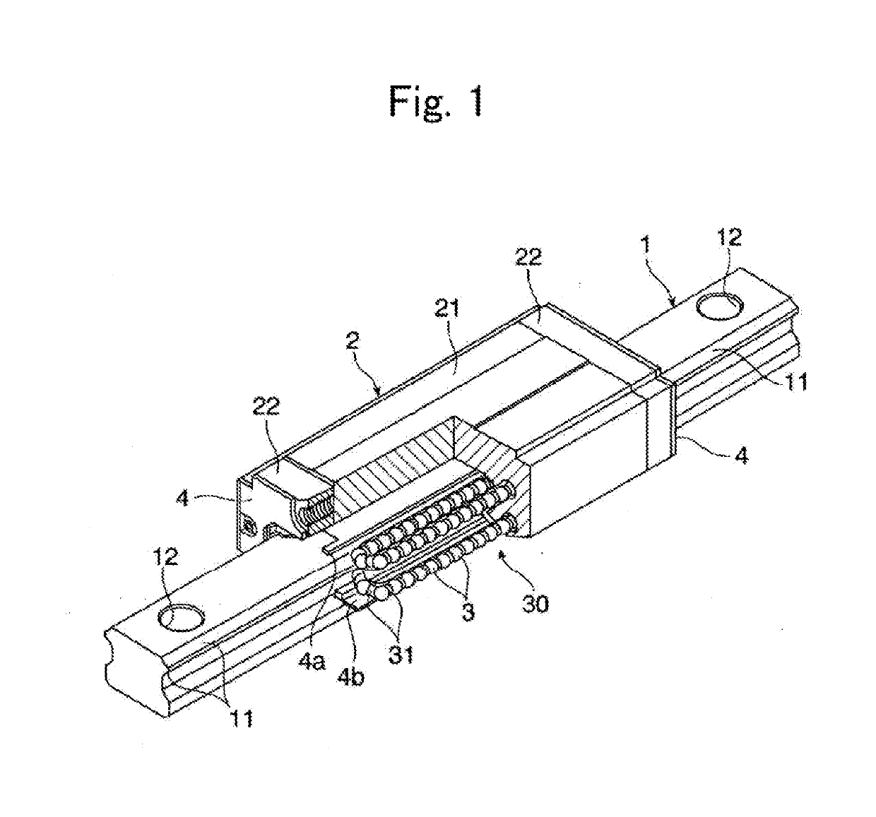
[0020]FIG. 1 is a perspective view for illustrating an example of a rolling guide device to which the present invention is applicable. The rolling guide device includes a track rail 1 and a moving block 2. The track rail 1 extends linearly. The moving block 2 is assembled to the track rail 1 through intermediation of a large number of balls 3 being rolling elements. The track rail 1 is laid on a fixed portion, and a movable body of a type among various types is mounted to the moving block 2, thereby being capable of guiding the movable body along the track rail 1 in a freely reciprocable manner.

[0021]The track rail 1 is formed into an elongated body having a substantially rectangular cross section. The track rail 1 has a plurality of bolt mounting holes 12, which are formed at predetermined intervals in a longitudinal dire...


PUM


Abstract

Provided is a rolling guide device which is capable of preventing uneven wear of a holding belt by alleviating a tensile force that acts on the holding belt when the holding belt circulates in an endless circulation path together with rolling elements. The endless circulation path has a guide groove configured to guide movement of the holding belt in the endless circulation path. A condition of tmax<δ is satisfied, where: tmax represents a maximum clearance between both end portions of the holding belt which are opposed to each other in the endless circulation path; δ is expressed by
δ=20π2(asinθ)2+(ccosθ)2dθ-20π2(csinθ)2+(bcosθ)2dθ;
2c represents an interval between the holding belt in a load path and the holding belt in a return path; A represents a depth to an arc top point of an outer peripheral surface of the guide groove in a direction change path; B represents a depth to an arc top point of an inner peripheral surface of the guide groove in the direction change path; “d” represents a thickness of the holding belt; and a=(A−d/2) and b=(B+d/2) are satisfied.

Description

TECHNICAL FIELD[0001]The present invention relates to a rolling guide device, which is configured to freely guide a work table of a machine tool or tables of various conveying devices along a track rail.BACKGROUND ART[0002]As a rolling guide device of this type, there has been known a rolling guide device disclosed in Patent Literature 1. This rolling guide device includes a track rail and a moving block. The track rail is laid on a fixed portion such as a bed. The moving block is freely movable along the track rail, and is capable of fixing a movable body such as a table being an object to be guided. The moving block is assembled to the track rail through intermediation of a plurality of rolling elements such as balls or rollers. A rolling surface for the rolling elements is formed on the track rail along a longitudinal direction of the track rail. The moving block has a rolling surface for the rolling elements, which is opposed to the rolling surface of the track rail. Further, th...

Claims


Application Information

Patent Timeline
IPC IPC(8): F16C29/06F16C33/38
CPCF16C29/0638F16C33/3825F16C29/06F16C33/42F16C33/54F16C29/065F16C29/0609
Inventor AOKI, SHINJIIRIKAWA, HIROKIAOYAMA, SHODAI
Owner THK CO LTD
Why Eureka
Try Eureka