Composite sucker rod assembly for underground wells

Inactive Publication Date: 2016-12-15
ELEVATORING SOLUTIONS USA INC
View PDF14 Cites 3 Cited by
  • Summary
  • Abstract
  • Description
  • Claims
  • Application Information

AI Technical Summary

Benefits of technology

[0020]A minimum number of strands are preferably bundled together to form a length of the composite sucker rod assembly. The plurality of parallel strands may be fully over-wrapped with an encapsulating layer of composite or polymer material that holds the bundle together and provides a wear resistant covering. The over-wrap may also be spaced incrementally to keep the bundle together, thereby increasing the overall stiffness of the sucker rod assembly and providing tailored dampening for compressive loads. The bundle of strands is preferably held together with a composite wrap spaced incrementally sufficient t

Problems solved by technology

Traditional metal sucker rods are heavy and subject to corrosion and fatigue failure, particularly at the threaded connections or due to stress corrosion cracking.
An unexpected broken sucker rod due to corrosion and/or fatigue is expensive to remove and replace.
Further, the weight of a metal sucker rod string limits its strength and fatigue life and can limit the depth which even large surface units can pump.
The weight of a steel sucker rod string can also overload and reduce the life of the surface unit and its components.
Fiberglass sucker rods do offer a weight reduction and corrosion resistance but have significant stretch and are prone to splitting and failing due to transient compression in the rod string.
Steel sucker rods are stiff and often cause excessive wear on the inside of the well casing where the well is not straight.
Additionally, the flex in the string induced by pumping causes metal fatigue which can cause t

Method used


Image

  • Composite sucker rod assembly for underground wells
  • Composite sucker rod assembly for underground wells
  • Composite sucker rod assembly for underground wells

Examples


Example

[0039]While the present invention is susceptible of embodiment in various forms, as shown in the drawings, hereinafter will be described the presently preferred embodiments of the invention with the understanding that the present disclosure is to be considered as an exemplification of the invention, and it is not intended to limit the invention to the specific embodiments illustrated.

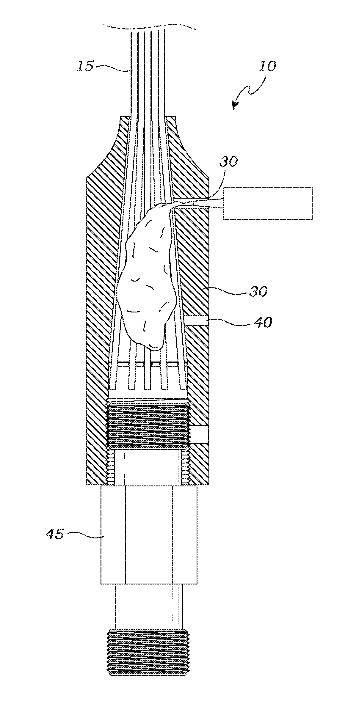
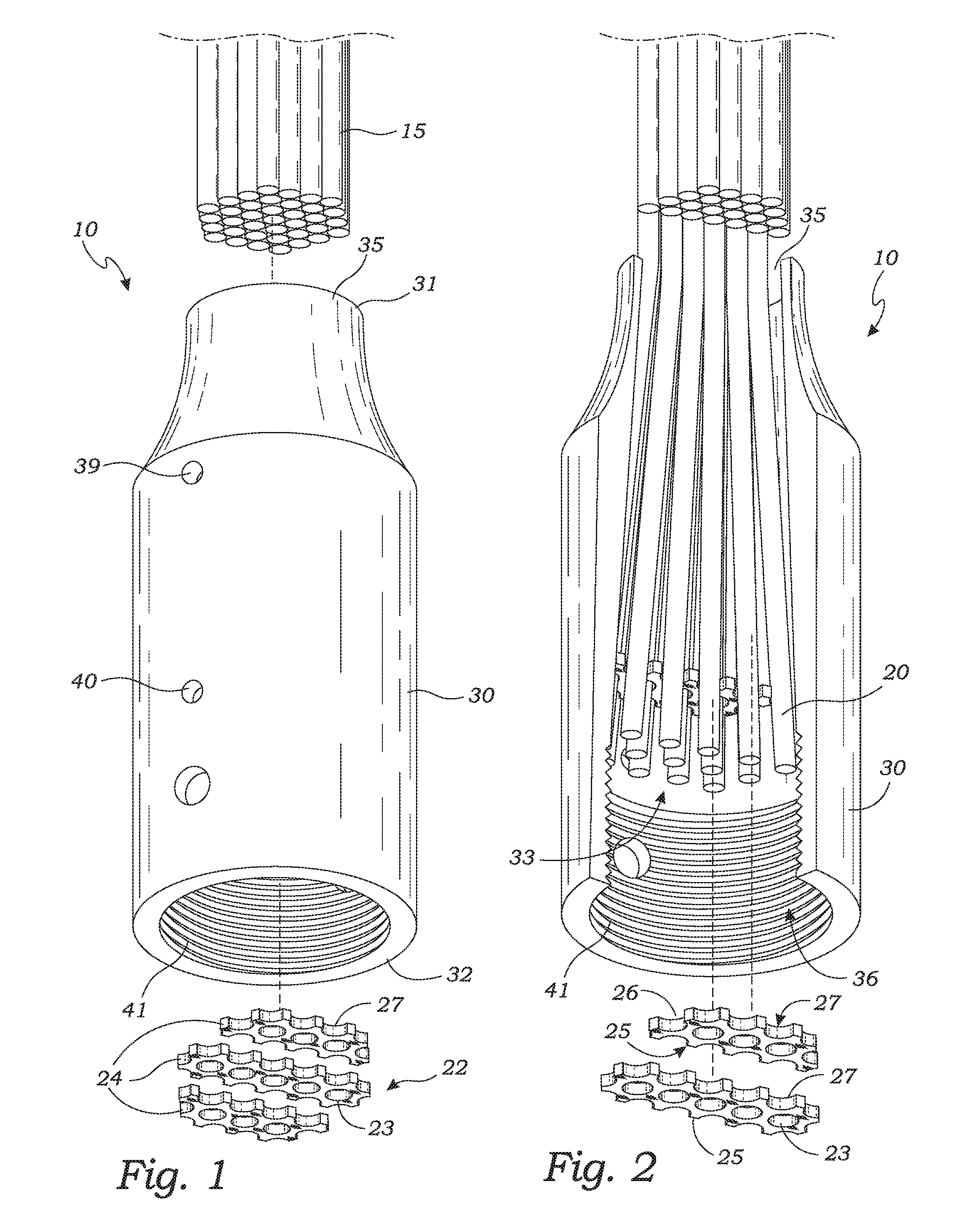
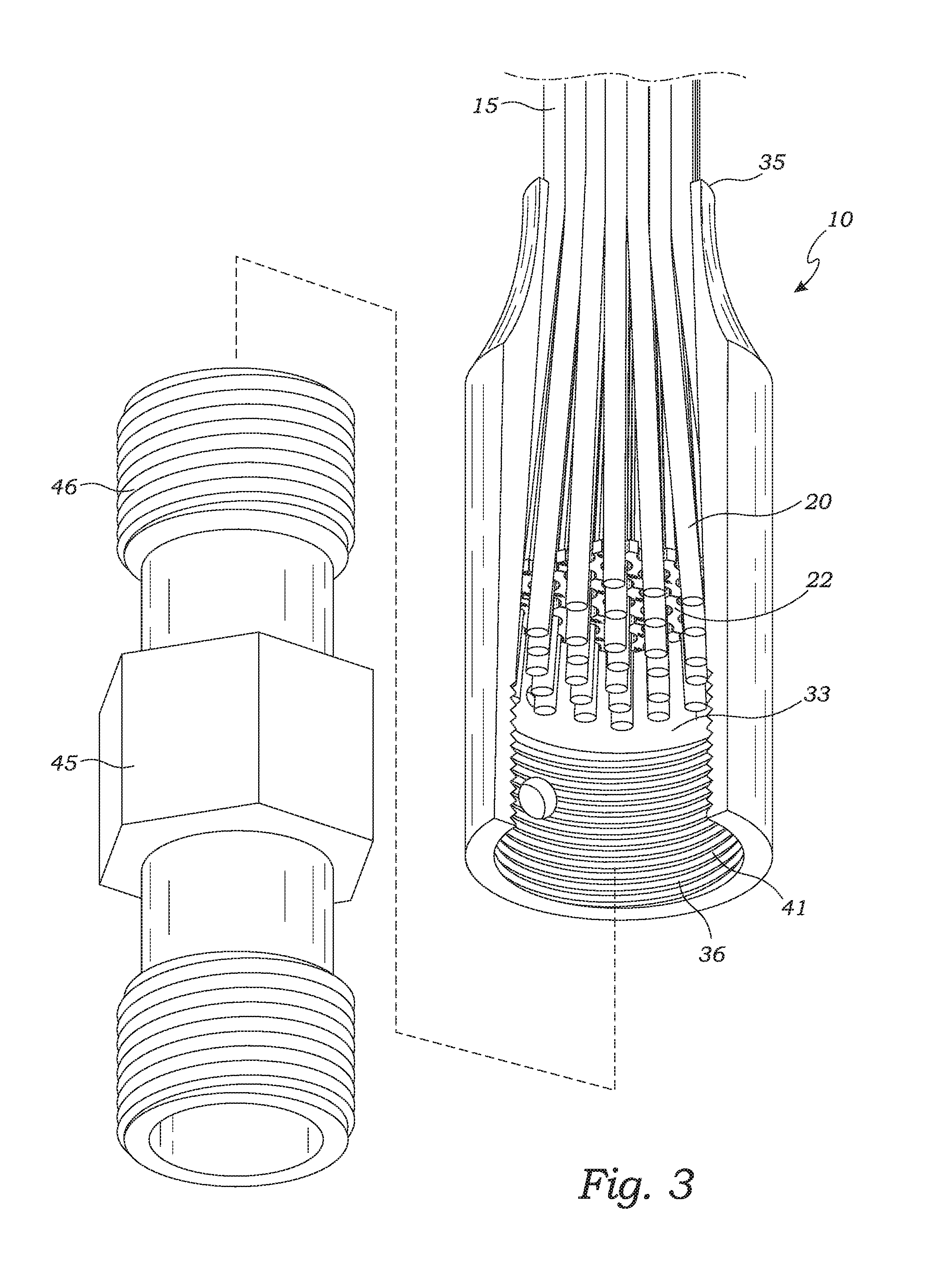
[0040]With reference to the figures, the sucker rod assembly 10 includes a plurality of strands 20 forming an elongate rod 15. The sucker rod assembly 10 further includes a terminus fitting 30 having a central cavity 33, a spreader plate 22, and connection member 45. A plurality of sucker rod assemblies are connected together to form a sucker rod string 11 to connect a vertical lift surface device to a down-hole pump unit.

[0041]As illustrated in FIGS. 1-14, the composite sucker rod assembly 10 comprises a plurality of generally round strands 20 that are bundled together to form the elongate rod 15. The ...


PUM


Abstract

A composite sucker rod assembly is provided for use in down-hole wells. The sucker rod assembly includes a plurality of parallel composite strands forming an elongate rod. Preferably, both ends of the rod are fitted with metallic terminus fittings. Each terminus fitting has a tapered cavity with a proximal opening to receive a rod end. The cavity is tapered so as to flare outwardly from said cavity's proximal opening toward the cavity's distal end. The sucker rod assembly further includes a spreader plate, preferably made up of a plurality of pieces, which has holes to receive and splay out the plurality rod strands. A hardened material, such as a hardened resin, is introduced into the cavity and allowed to harden to affix the rod to the terminus fitting. Preferably the hardened resin is compressed by a connection member.

Description

BACKGROUND OF THE INVENTION[0001]The present invention relates generally to sucker rod engineering and design. More particularly, the present invention relates to a composite sucker rod assembly for use in down-hole vertical lift oil extraction.[0002]Sucker rods for use with vertical lift rod pumps, also referred to as surface units, rocking horse, or pump jacks are typically made from individual lengths of steel rod sections that are connected together by threaded couplings. The individual sucker rods are typically 25 feet, 30 feet or 37.5 feet in length and are connected together with couplings to form a sucker rod string. A typical sucker rod string is from 700 to 10,000 feet or more in length. The sucker rod string connects the vertical lift surface device to the down-hole pump unit. Traditional metal sucker rods are heavy and subject to corrosion and fatigue failure, particularly at the threaded connections or due to stress corrosion cracking. An unexpected broken sucker rod du...

Claims


Application Information

Patent Timeline
IPC IPC(8): E21B17/00E21B43/12
CPCE21B43/126E21B17/00E21B43/127E21B17/0426
Inventor SJOSTEDT, ROBCOOK, HUGH
Owner ELEVATORING SOLUTIONS USA INC
Why Eureka
Try Eureka