Eureka AIR delivers breakthrough ideas for toughest innovation challenges, trusted by R&D personnel around the world.

Orthopedic clamping devices

Active Publication Date: 2019-04-18
THE ORTHOPAEDIC IMPLANT CO
View PDF16 Cites 7 Cited by
  • Summary
  • Abstract
  • Description
  • Claims
  • Application Information

AI Technical Summary

Benefits of technology

The present disclosure provides a clamp for affixing at least two fixation members relative to each other. The clamp includes a first clamp and a second clamp with inner and outer jaws that define recesses that form a clamping axis. A post extends from the second outer jaw and is fixed to the second inner jaw and the first outer jaw. A clamping nut is threadably coupled to the post and exerts a clamping force to fix the fixation members. The clamp can be used to fix a plurality of fixation members. The technical effect of the clamp is to provide a reliable and adjustable tool for fixing multiple fixation members in a simple and efficient manner.

Problems solved by technology

A drawback of current orthopedic clamps is that their configuration tends to allow the bars or rods to decouple from the jaws of the clamp when the assembly and tissue segments are adjusted.
Another drawback of current orthopedic clamps is that because they rely on clamping surfaces or recesses of the jaws that are offset from the clamping axis, the backside of the clamps must abut to pivot the jaws closed.

Method used


Image

  • Orthopedic clamping devices
  • Orthopedic clamping devices
  • Orthopedic clamping devices

Examples


Embodiment Construction

[0041]When introducing elements of various embodiments of the present disclosure, the articles “a,”“an,”“the,” and “said” are intended to mean that there are one or more of the elements. The terms “comprising,”“including,” and “having” are intended to be inclusive and mean that there may be additional elements other than the listed elements. Any examples of parameters are not exclusive of other parameters of the disclosed embodiments. Components, aspects, features, configurations, arrangements, uses and the like described, illustrated or otherwise disclosed herein with respect to any particular embodiment may similarly be applied to any other embodiment disclosed herein.

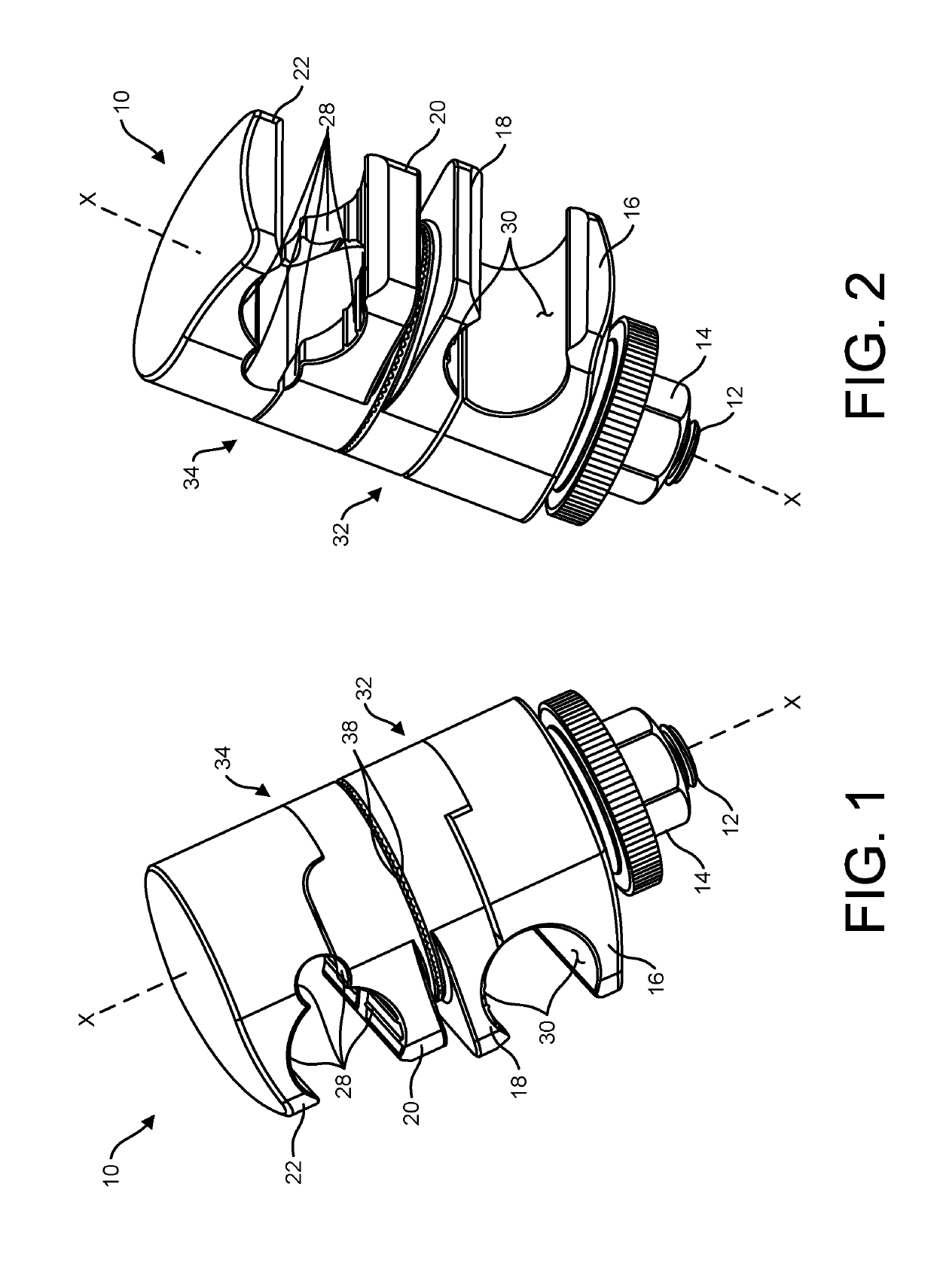
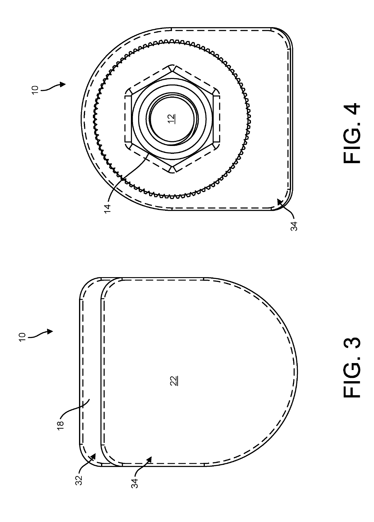
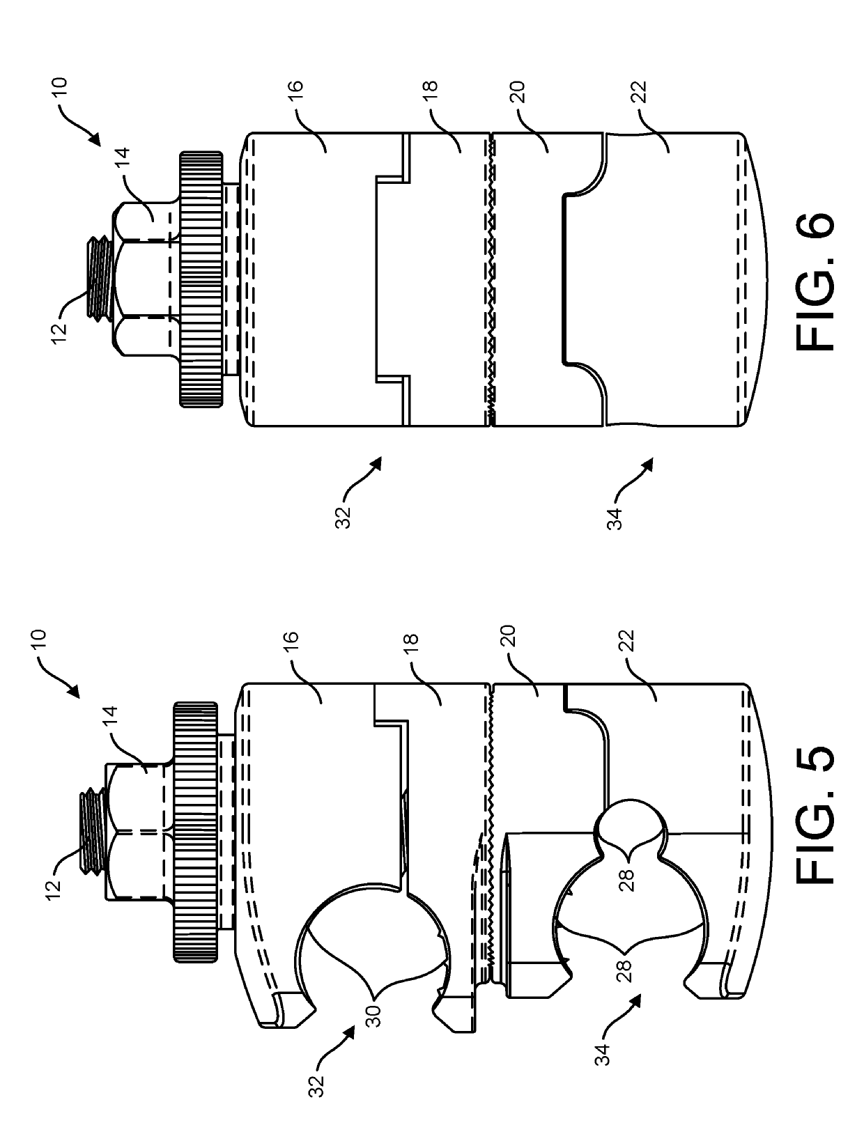
[0042]The present disclosure provides orthopedic clamping devices or systems that direct all, or at least the majority, of the fixation clamping pressure to the clamping or engagement surfaces of the jaws thereof, and thereby to a fixation member (e.g., a rod or pin) therebetween. Further, the present disclosure prov...


PUM


Abstract

An orthopedic clamp for affixing at least two fixation members relative to each other is disclosed. The clamp includes a first clamp comprising first outer and inner jaws that define first clamping surfaces that form a first recess, and a second clamp comprising second outer and inner jaws that define second clamping surfaces that form a second recess. The clamps also include a post extending from the second outer jaw and through the second inner jaw, the first inner jaw and the first outer jaw. The post defines a clamping axis, and the second recess defines an axis that intersects the clamping axis. The clamp further includes a clamping nut threadably coupled to the post configured to exert a clamping force to the first and second clamps to fix at least one of a first fixation member within the first recess and a second fixation member within the second recess.

Description

CROSS-REFERENCE TO RELATED APPLICATION[0001]This present application perfects and claims the benefit of U.S. Provisional Patent Application No. 62 / 571,571, filed on Mar. 9, 2018, entitled Orthopedic Clamping Devices, the contents of which is hereby expressly incorporated herein by reference in its entirety.FIELD OF THE INVENTION[0002]The present disclosure is generally directed to clamps. More particularly, the present disclosure is directed to clamping devices of external fixation systems for stabilizing tissue, such as bone fragments.BACKGROUND OF THE INVENTION[0003]External fixation systems use pins, wires, rods or other fixation elements to stabilize and / or manipulate tissue segments, such as bone segments. These fixation elements are typically held in space relative to each other by a fixation frame. The frame is commonly made up of rings, struts, bars or other structural members. The simplest frame is usually made up of bars (sometimes referred to as rods). To hold the bars to...

Claims


Application Information

Patent Timeline
IPC IPC(8): A61B17/64
CPCA61B17/645A61B2017/00477A61B17/6466A61B90/57
Inventor NEMOVICHER, ITAIMARTENS, TODDMULLANEY, MICHAEL W.
Owner THE ORTHOPAEDIC IMPLANT CO
Why Eureka
Eureka Blog
Learn More