Spray can

Inactive Publication Date: 2019-04-25
CHU
View PDF2 Cites 1 Cited by
  • Summary
  • Abstract
  • Description
  • Claims
  • Application Information

AI Technical Summary

Benefits of technology

[0006]The main objective of the present invention is to provide a spray can that is able

Problems solved by technology

The first body and the second body made of plast

Method used


Image

  • Spray can
  • Spray can
  • Spray can

Examples


Example

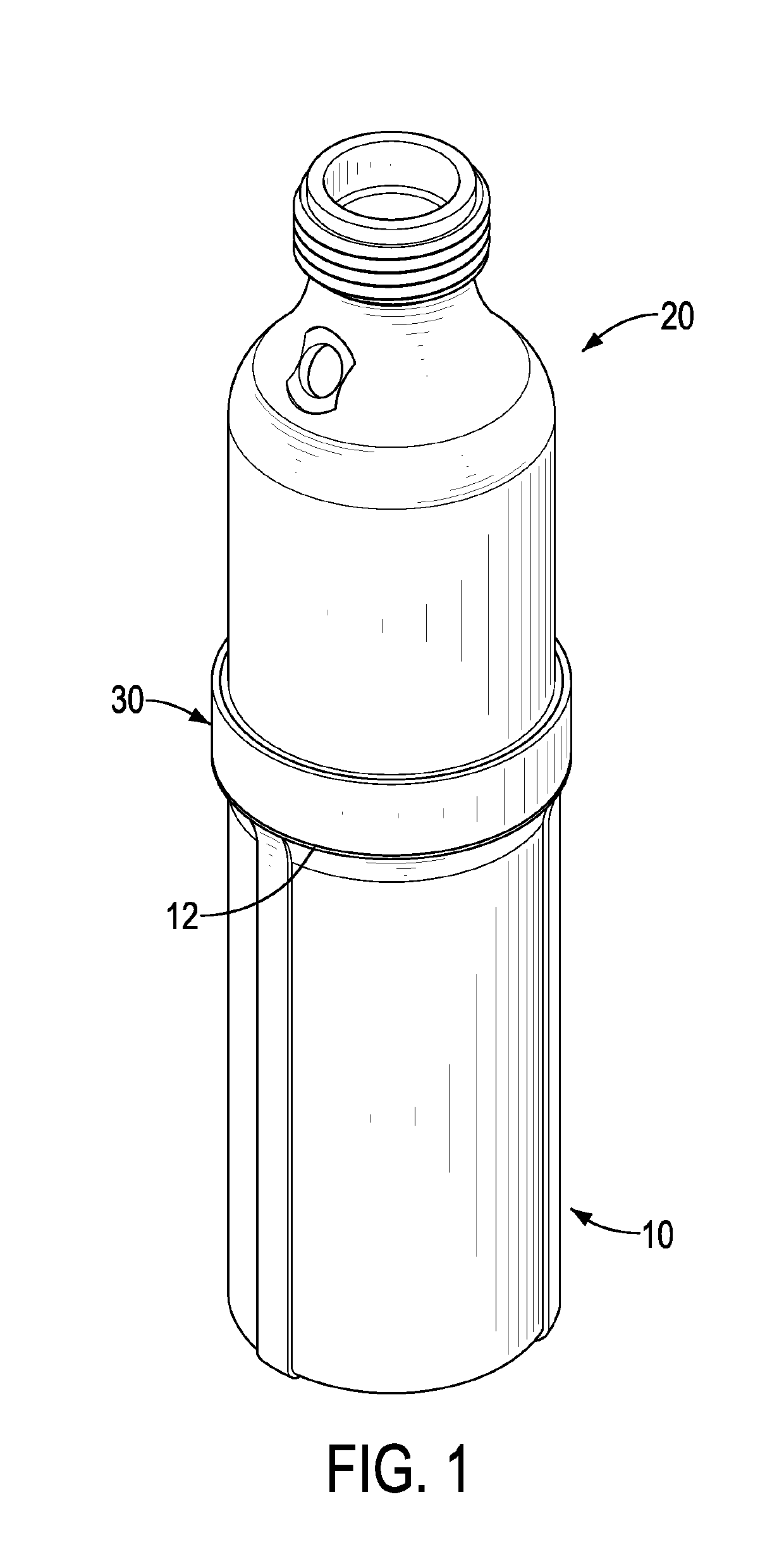
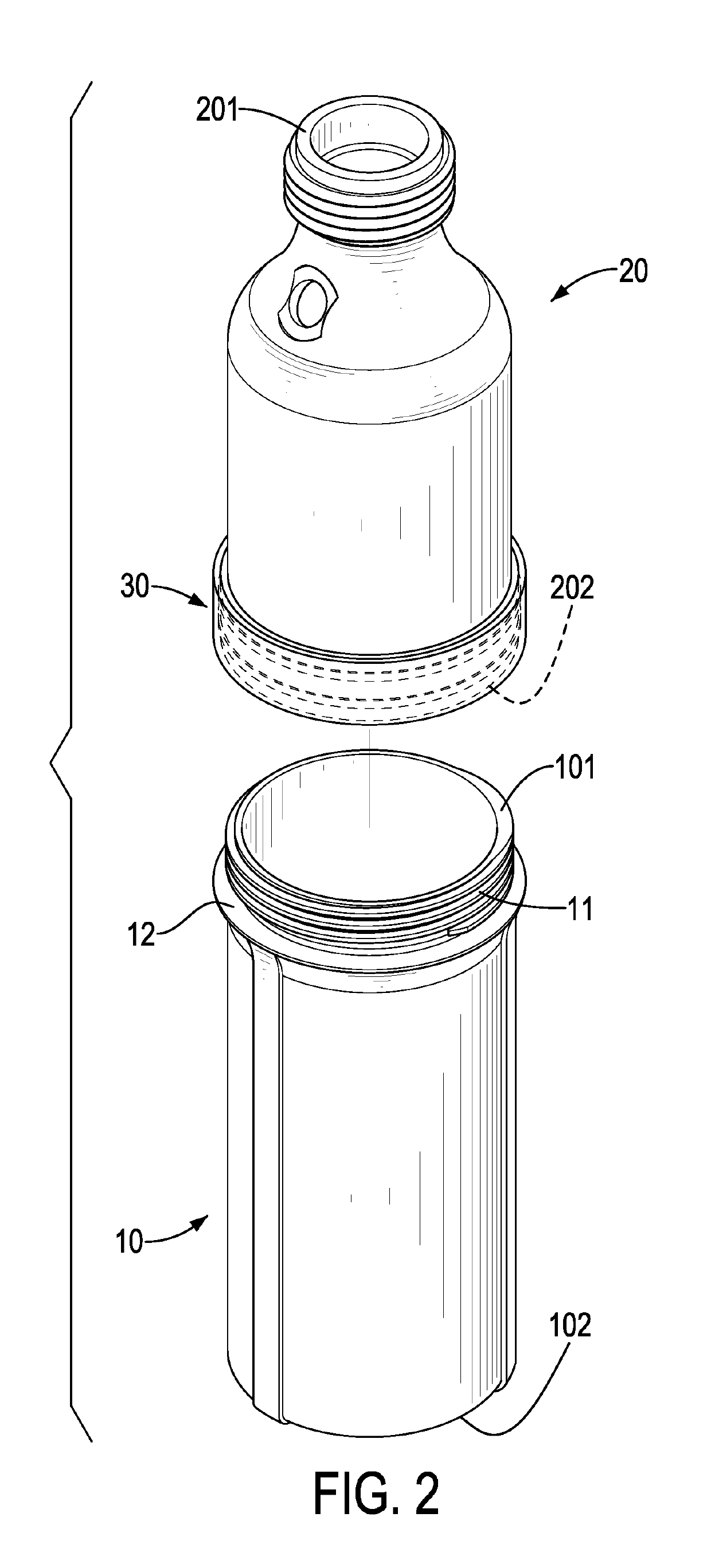
[0017]With reference to FIGS. 1 and 2, a spray can in accordance with the present invention has a first body 10, a second body 20, and a reinforcing sleeve 30. The second body 20 is mounted to the first body 10. The reinforcing sleeve 30 is sleeved on the second body 20. The second body 20 and. the reinforcing sleeve 30 are fixed together.

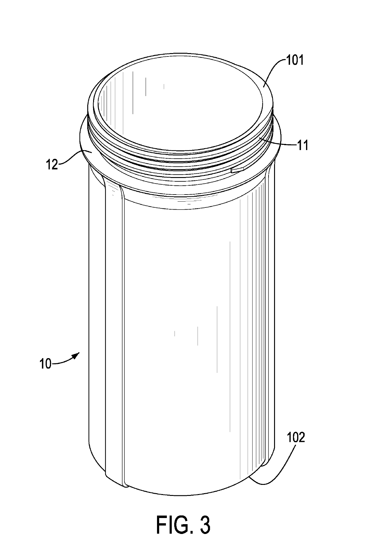
[0018]With reference to FIGS. 2, 3, and 4, the first body 10 is made of plastic. The first body 10 has a lengthwise direction, an inner circumference, an outer circumference, a first end 101, a second end 102, an assembling portion 11, an annular abutting portion 12, and a gas injection hole 13. The inner circumference and the outer circumference of the first body 10 are opposite each other. The first end 101 and the second end 102 of the first body 10 are opposite in the lengthwise direction of the first body 10. The assembling portion 11 is disposed at the first end 101 of the first body 10. The assembling portion 11 has a thread formed on the ou...


PUM


Abstract

A spray can has a first body, a second body, and a reinforcing sleeve. The first body is made of plastic. The second body is made of plastic and is connected to the first body. The reinforcing sleeve is made of metal. The reinforcing sleeve is sleeved on the second body and is adjacent to a joining portion where the second body is connected to the first body. The first body and the second body made of plastic save a lot of material and machining expenses. The reinforcing sleeve8 ade of metal enhances the rigidity of the joining portion of the first body and. the second body.

Description

BACKGROUND OF THE INVENTION1. Field of the Invention[0001]The present invention relates to a container structure of a spray can that may be manufactured at a reduced manufacturing cost.2. Description of Related Art[0002]A spray can is a container filled with compressed fluid and content such as paint, oil, or hair styling products. For improving rigidity of the spray can, a traditional spray can is integrally made of metal. Since the traditional spray can is a metallic integral structure, it is able to sustain pressure caused by the compressed fluid. However, the traditional spray can of an integral structure can be refilled only by specialized tools. Therefore, the traditional spray can is inconvenient for refilling.[0003]In order to mitigate a problem that the traditional spray can is inconvenient for refilling, a conventional spray can with two detachable bodies has been invented. The conventional spray can has an upper body and a lower body. The lower body is detachably connecte...

Claims


Application Information

Patent Timeline
IPC IPC(8): B65D83/38B65D83/42
CPCB65D83/38B65D83/42
Inventor CHU, BO-LANG
Owner CHU
Why Eureka
Try Eureka