Draw for baler

A traction device and baler technology, applied in agricultural machinery, packaging, applications, etc., can solve problems such as damage to tie rods, excessive consumption of time and cost, and wheels that cannot be kept in a horizontal state, so as to increase quality and durability and reduce costs. and time effect

Inactive Publication Date: 2015-09-02
ASIA TECH CO LTD
View PDF8 Cites 1 Cited by
  • Summary
  • Abstract
  • Description
  • Claims
  • Application Information

AI Technical Summary

Problems solved by technology

[0009] However, in Korea, the work area is not wide, the boundary between workplaces such as riverbanks protrudes, and the workplaces have inclined surfaces or concave and convex parts, and problems occur when the baler is pulled by agricultural machinery
[0010] In addition, since the connecting portion between the tie rod and the farm machine is excessively bent when the farm machine turns in a narrow workplace, the universal joint for transmitting the power of the farm machine may be damaged, and the farm machine or the tie rod may pass through the tie rod Interference with agricultural machinery and damage
[0011] When the wheels of the baler are not kept level and the opposite surface of the baler is in the process of crossing the boundary of the work site or in the process of passing the uneven part, the baler may roll badly
During this process, since the linear tie rods cannot cope with the rolling along their length, the tie rods can be severely twisted and thus can be damaged
[0012] In particular, since the tie rod cannot cope with the rolling of the baler, and is twisted when the agricultural machine passes a boundary point or a concave-convex portion of the workplace, or performs work on an inclined surface, twisting is generated and thus transferred to the agricultural machine The connecting part of the agricultural machinery, the stress caused by twisting is transferred to the agricultural machinery and the connecting part of the agricultural machinery, thereby damaging the agricultural machinery
[0013] Since agricultural machinery cannot turn immediately in a narrow area, and should frequently move forward and backward in order to make a turn due to an inappropriate workplace, work efficiency is low
In addition, time and costs are excessively consumed due to periodic maintenance due to damage caused to traction units and agricultural machinery during work

Method used


Image

  • Draw for baler
  • Draw for baler
  • Draw for baler

Examples


Embodiment Construction

[0022] Hereinafter, the configuration and operation of the present invention for achieving the objects will be described with reference to the accompanying drawings.

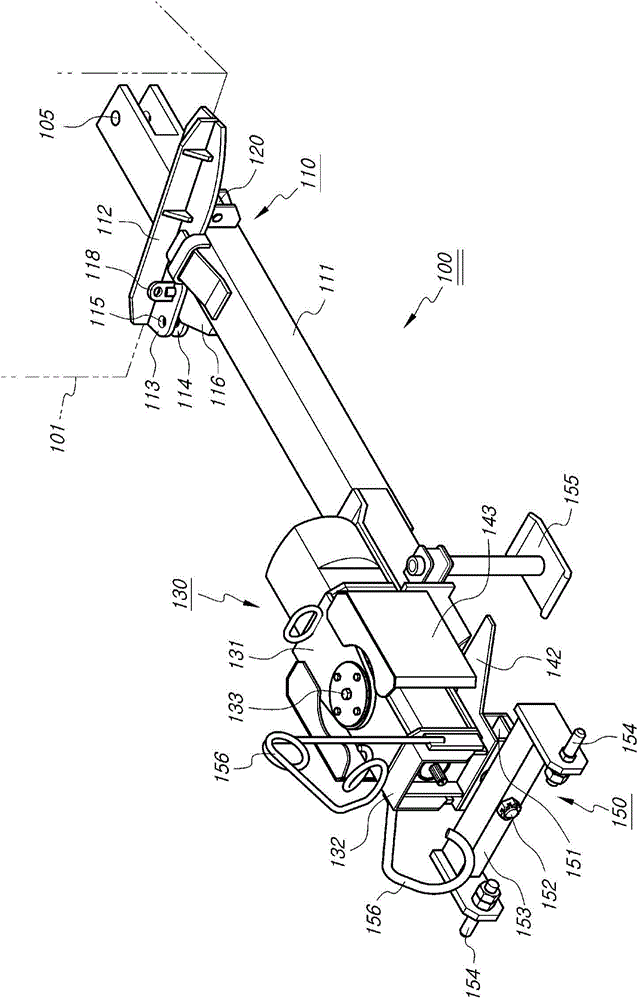
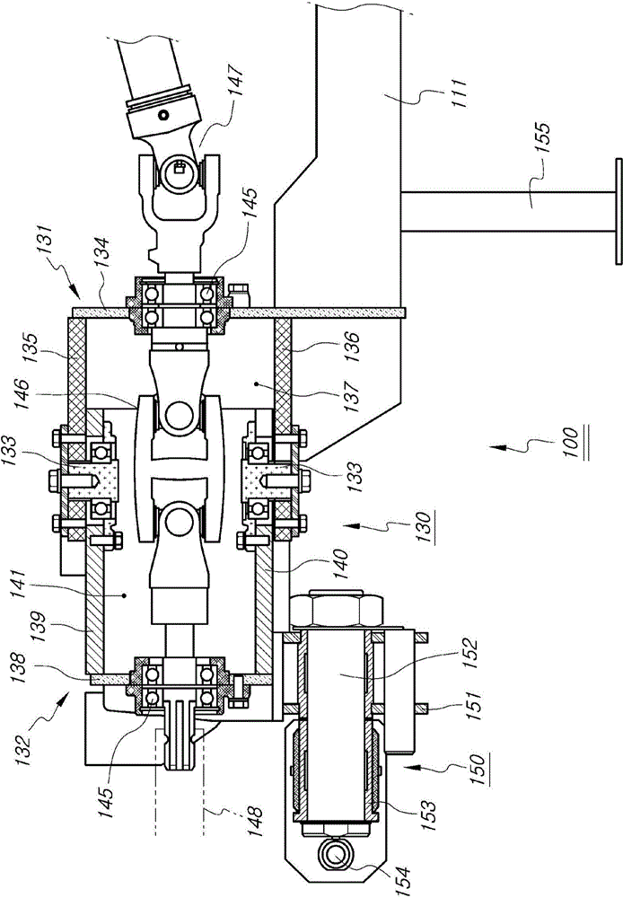
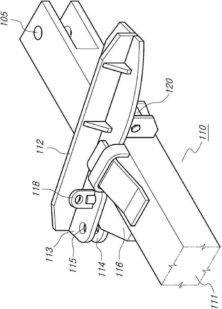
[0023] figure 1 is a perspective view showing the appearance of the pulling device for a baler according to the present invention. figure 2 is a cross-sectional view showing a bending unit of a pulling device for a baler according to the present invention. image 3 is a perspective view showing a baler mounting unit of a pulling device for a baler according to the present invention. Figure 4 is a plan view showing a baler mounting unit of a pulling device for a baler according to the present invention. Figure 1 to Figure 4 will be co-referenced.

[0024] The pulling device 100 for a baler according to the present invention includes: a baler installation unit 110 installed to the baler 101 so that a pulling position and a working position can be selected; The bending unit 130 is used to bend left and right...


PUM


Abstract

The invention discloses a draw for a baler, comprising: a baler mounting unit which is mounted to the baler so as to allow the selection and determination of a pulling position or a work position; a bending unit which is mounted to the front side of the baler mounting unit and bends towards left or right with respect to the center of a connecting shaft of an agricultural machine; and a rolling unit which is mounted to the front side of the bending unit so as to handle possible rollings generated while passing recessed or raised parts or slopes, provided that the rolling unit has already been connected to a agricultural machine. The draw herein bends and rolls towards the left side and the right side of the axis of the draw so as so allow the agricultural machine to swerve in narrow places and enable the agricultural machine to continue working upon passing recessed or raised portions or slops or to move without being deformed.

Description

technical field [0001] The present invention relates to a draw device for a baler, and more particularly to an improved draw device for a baler that can move freely to the left and right sides of an agricultural machine and can freely Swivels to the lateral side of the axis of the agricultural machine, making it easy to work on inclined surfaces and in confined spaces due to the small turning radius in confined spaces. Background technique [0002] Various working tools required for agriculture are coupled to the front and rear sides of agricultural machinery such as tractors, so that power required to operate the working tools can be supplied to the working tools, and the working tools connected to the agricultural machinery can be Pulling, so that agricultural mechanization can be realized and farming can be conveniently carried out. [0003] Various types of working implements such as tractors and balers for producing straw and various hays that are used as livestock fee...

Claims


Application Information

Patent Timeline
Patent Type & Authority Applications(China)
IPC IPC(8): A01B59/04
CPCA01B59/04A01B59/042A01F15/08
Inventor 金东珉
Owner ASIA TECH CO LTD
Why Eureka
Try Eureka