
Eureka
For R&D, Eureka makes reading and utilizing patents & technical documents easy.
Eureka AIR
Designed for self-driven R&D workflows. Generate viable solutions, solve complex R&D challenges, empower your innovation with AI.

Eureka Materials
Designed for material experts only. Revolutionize your material R&D, from search, analyze, to developing new materials.

TechResearch
Generate reliable direction feasibility study reports for your R&D in just a few steps.

TechSeek
Discover and master advanced knowledge NOW. Basics, ideas, possibilities, all at once.

TechMind
As an expert in R&D Theories, TechMind can generates customized viable solutions instantly.

TechRisk
Analyze your overall solution with one click, know your potential R&D risks in advance.

TechMonitor
Get weekly tech updates, stay abreast of the latest tech innovations and key insights.
Linear vibration generator including plate type spring having bent portion
- Summary
- Abstract
- Description
- Claims
- Application Information
AI Technical Summary
Benefits of technology
Problems solved by technology
Method used
Image

Examples
first embodiment
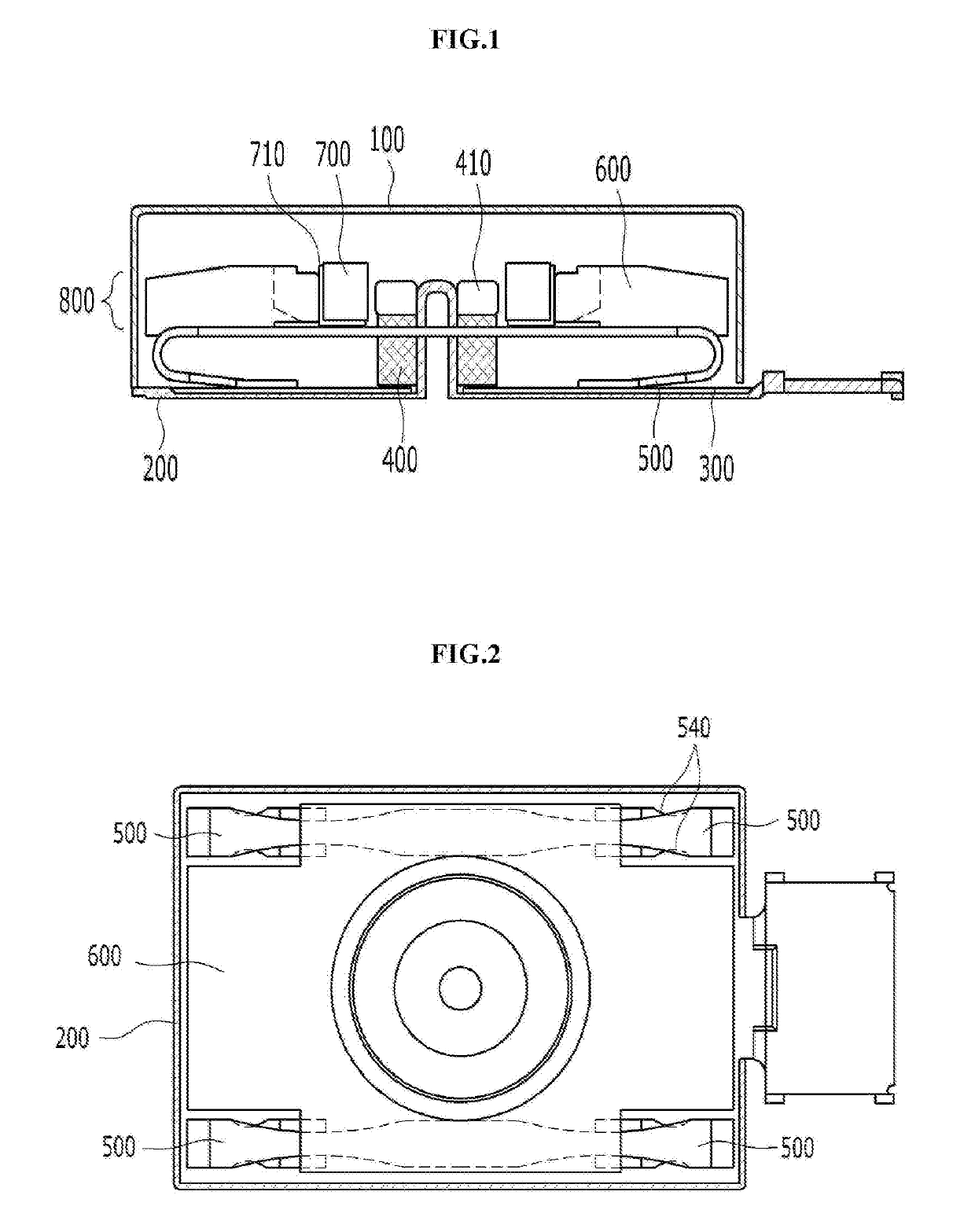
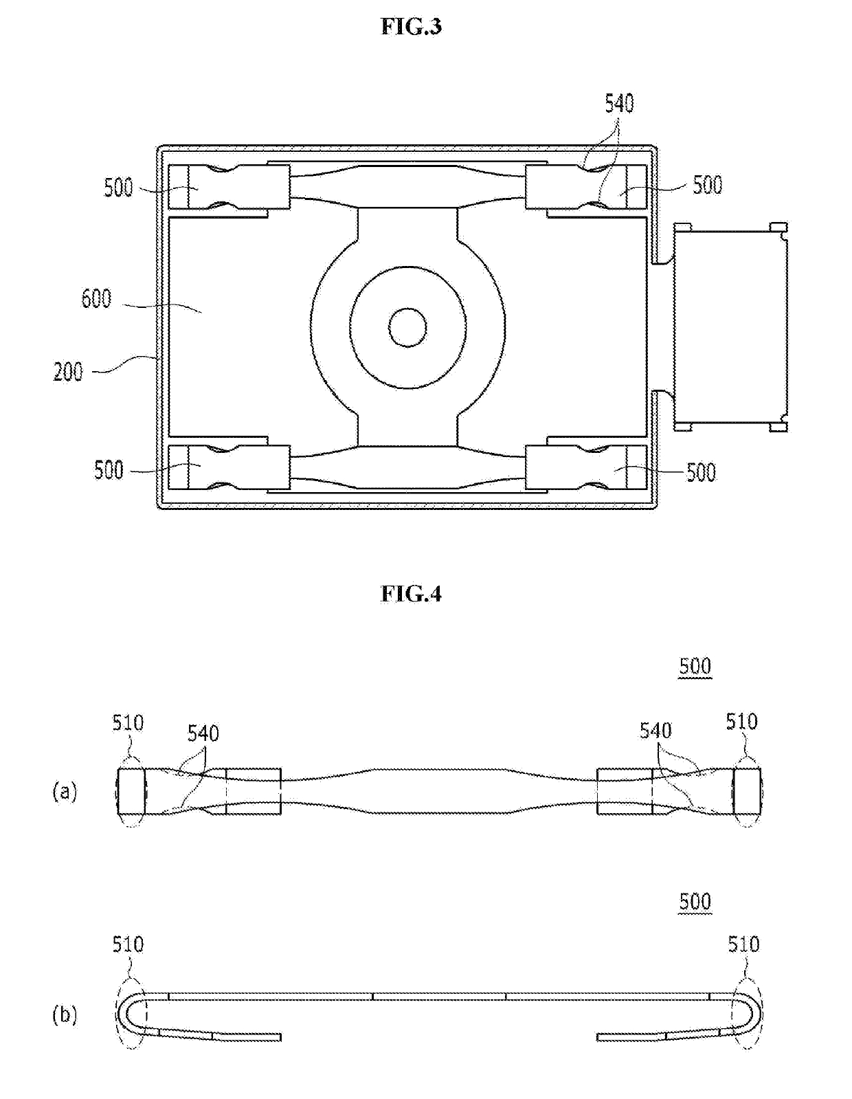
[0036]As shown in FIGS. 1 to 3, a linear vibration generator according to the present invention is provided not with spiral-shaped springs, but with plate type springs having a symmetrical structure.
[0037]The linear vibration generator according to the first embodiment of the present invention includes a case 100 for covering top and side portions thereof, a bracket 200 coupled to the underside of the case 100, a coil 400 fixed to one side of a top surface of the bracket 200 and receiving external power from an FPCB 300, a plate type spring 500 having bent portions 510 and configured to allow one end thereof to be fixed to a vibrator 800, and the vibrator 800 having a weight 600 fixed to one end of the plate type spring 500 and a magnet 700 insertedly fixed to a hollow portion 610 of the weight 600.
[0038]Under the above-mentioned configuration, now, an operating process of the linear vibration generator according to the first embodiment of the present invention will be explained.
[00...
second embodiment
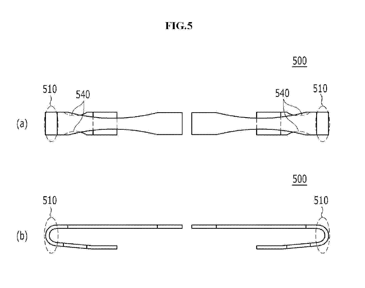
[0060]As shown in FIGS. 8 and 9, the linear vibration generator according to the present invention is provided not with spiral-shaped springs, but with symmetrically structured plate type spring having a support cup 520 formed on a center portion thereof.
[0061]As shown in (a) of FIG. 9, the linear vibration generator according to the second embodiment of the present invention includes a case 100 for covering top and side portions thereof, a bracket 200 coupled to the underside of the case 100, a coil 400 fixed to one side of a top surface of the bracket 200 and receiving external power from an FPCB 300, a plate type spring 500 having bent portions 510 and a support cup 520 and configured to allow one end thereof to be fixed to a vibrator 800, and the vibrator 800 having a weight 600 fixed to one end of the plate type spring 500 and a magnet 700 insertedly fixed to a hollow portion 610 of the weight 600.
[0062]The weight 600 has second machined portions formed on both sides of the cen...
third embodiment
[0077]FIG. 12 is a front sectional view showing a linear vibration generator according to the present invention, wherein the plate type spring is fixed to an upper portion of a case and a weight hangs on the plate type spring.
[0078]As shown in FIG. 12, one end of each plate type sub-spring is coupled to the vibrator 800, and the other end thereof is fixed to the case 100. Contrarily, of course, one end of each plate type sub-spring is coupled to the vibrator 800, and the other end thereof is fixed to the bracket 200, so that the plate type spring 500 is located between the vibrator 800 and the bracket 200.
[0079]As described above, the linear vibration generator according to the present invention is configured to improve the structures of the springs disposed therein, thereby preventing the weight of the vibrator from coming into contact with the inner surface of the case due to the twist of the vibrator and avoiding unnecessary generation of noise and damage of the vibrator.
PUM
 Abstract
Description
Claims
Application Information
 - R&D Engineer
- R&D Manager
- IP Professional
- Industry Leading Data Capabilities
- Powerful AI technology
- Patent DNA Extraction
Browse by: Latest US Patents, China's latest patents, Technical Efficacy Thesaurus, Application Domain, Technology Topic, Popular Technical Reports.
© 2024 PatSnap. All rights reserved.Legal|Privacy policy|Modern Slavery Act Transparency Statement|Sitemap|About US| Contact US: help@patsnap.com