

Inkjet printer with wiper for nozzle surface
a technology of nozzle surface and inkjet printer, which is applied in the direction of printing mechanism, printing, power drive mechanism, etc., can solve the problem of increasing the frequency of inkjet head replacemen
- Summary
- Abstract
- Description
- Claims
- Application Information
AI Technical Summary
Benefits of technology
Problems solved by technology
Method used
Image

Examples
first embodiment
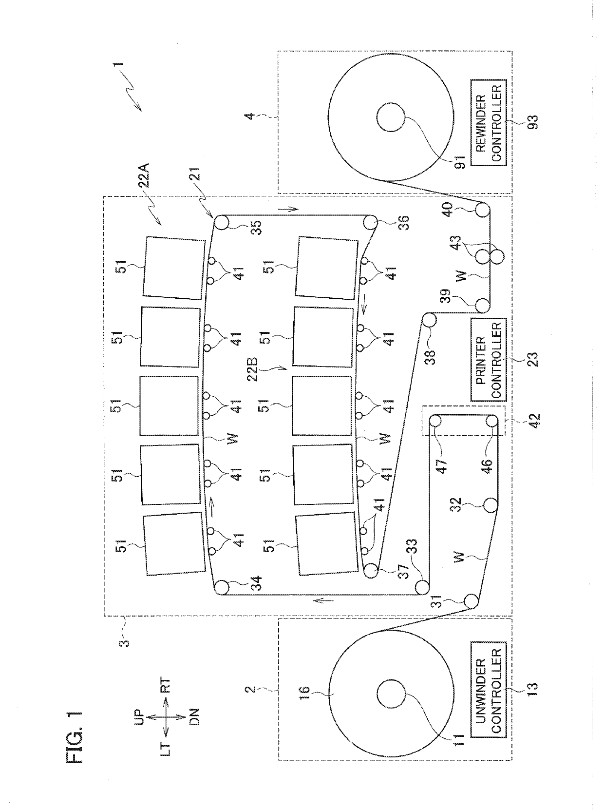
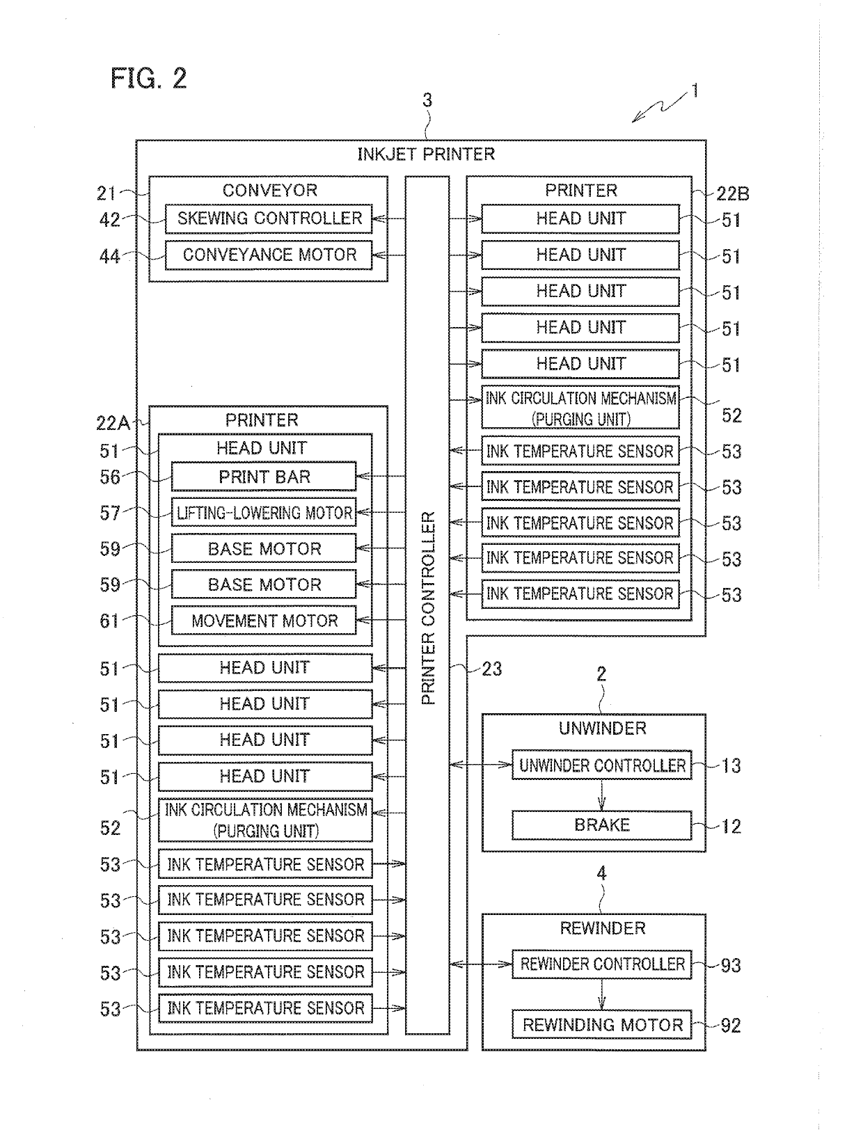
[0041]As illustrated in FIGS. 1 and 2, a print system 1 includes an unwinder 2, an inkjet printer 3, and a rewinder 4.
[0042]The unwinder 2 unwinds a web W being a long print medium made of film, paper, or the like to the inkjet printer 3. The unwinder 2 includes a web roll support shaft 11, a brake 12, and an unwinder controller 13.
[0043]The web roll support shaft 11 rotatably supports a web roll 16. The web roll 16 is the web W wound into a roll.
[0044]The brake 12 applies brake force to the web roll support shaft 11. Tension is thereby applied to the web W between the web roll 16 and a pair of conveyance rollers 43 of the inkjet printer 3 to be described later.
[0045]The unwinder controller 13 controls the brake 12. The unwinder controller 13 includes a CPU, a RAM, a ROM, a hard disk drive, and the like.
[0046]The inkjet printer 3 prints an image on the web W while conveying the web W unwound from the unwinder 2. The inkjet printer 3 includes a conveyor 21, printers 22A, 22B, and a ...
second embodiment
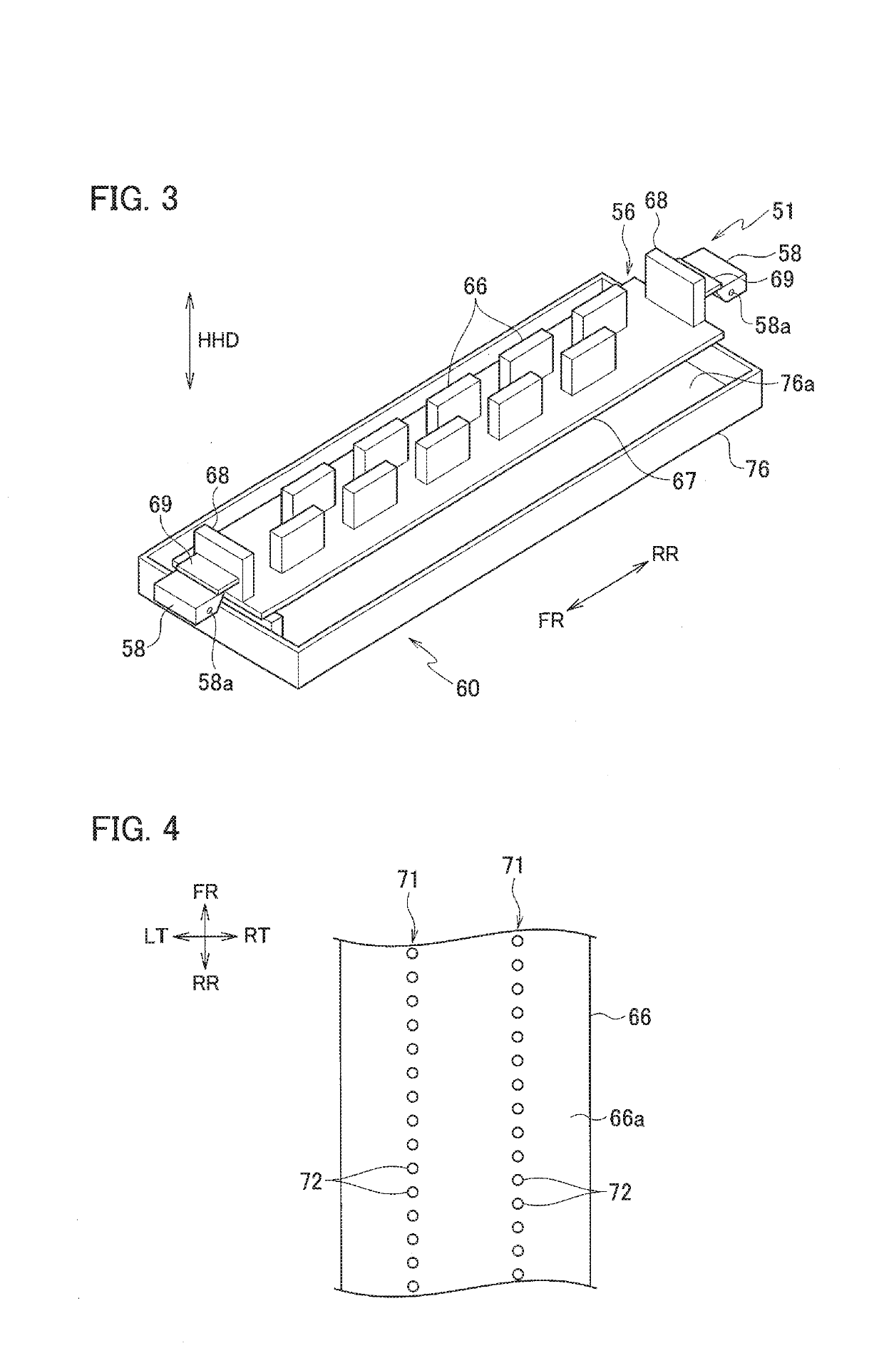
[0150]In the second embodiment, the orientation of the wipers 82 in each head unit 51 in which the nozzle surfaces 66a are tilted is adjusted depending on the temperature of the ink supplied to the inkjet heads 66. Specifically, in each head unit 51 in which the nozzle surfaces 66a are tilted, the adjustment is performed such that the higher the temperature of the ink supplied to the inkjet heads 66 is, the greater the tilt angle α of the wipers 82 is set.
[0151]The higher the temperature of the ink is, the lower the viscosity of the ink is and the ink attached to the nozzle surfaces 66a tends to run down. Meanwhile, the greater the tilt angle α of the wipers 82 is, the easier it is for the wipers 82 to push the ink toward the upper side of the nozzle surfaces 66a in the wiping. Accordingly, increasing the tilt angle α of the wipers 82 with an increase in the temperature of the ink as described above suppresses the case where the wipers 82 cannot sufficiently push up the ink running ...
third embodiment
[0159]As illustrated in FIGS. 19 and 20, each of the maintenance units 60B in the third embodiment includes an ink receptor 111, wiper units 112A, 112B, and a wiper driver 113.
[0160]Here, the maintenance units 60B in the leftmost head unit 51 and the second head unit 51 from the left in which the nozzle surfaces 66a are tilted downward while extending to the left are installed with their orientation turned by 180 degrees in the plan view from the orientation of the maintenance units 60B in the rightmost head unit 51 and the second head unit 51 from the right in which the nozzle surfaces 66a are tilted downward while extending to the right.
[0161]Note that the orientation of the maintenance unit 60B in the center head unit 51 may be the same as the orientation of the maintenance units 60B in the head units 51 in which the nozzle surfaces 66a are tilted downward while extending to the left or as the orientation of the maintenance units 60B in the head units 51 in which the nozzle surfa...
PUM
 Abstract
Description
Claims
Application Information