Connector and connector structure

a technology of connectors and connectors, applied in the direction of coupling bases/cases, coupling device connections, electrical devices, etc., can solve the problems of receptacles and housing receptacles and housings rumbling against each other, etc., to reduce cost, reduce rattling of receptacles and housings, the effect of reducing costs

Active Publication Date: 2019-05-02
SUMITOMO WIRING SYST LTD
View PDF22 Cites 6 Cited by
  • Summary
  • Abstract
  • Description
  • Claims
  • Application Information

AI Technical Summary

Benefits of technology

[0009]In the waterproof connector, the seal ring is fit on the outer surface of the housing to provide sealing between the housing and the receptacle. In the case of changing the waterproof connector to have non-waterproof specifications, the seal ring fit on the rear side of the outer surface of the housing (hereinafter, referred to as a “rear side of the retainer mounting hole”) is unnecessary. In changing to the non-waterproof specifications, a clearance may be formed between the inner surface on the opening side of the receptacle in the fitting state and the rear side of the retainer mounting hole. Thus, the receptacle and the housing may rattle against each other. However, in the present invention, the restricting portion projects on the rear side of the retainer mounting hole and is arranged to contact the inner surface on the opening side of the receptacle in the fitting state. Thus, rattling of the receptacle and the housing can be suppressed.
[0010]According to the above configuration, the non-waterproof connector can be configured without being accompanied by shape changes of parts other than the rear side of the retainer mounting hole, and the retainer can have the same shape and be commonly used between the non-waterproof connector and the waterproof connector. As a result, in changing the waterproof connector to have the specifications of the non-waterproof connector, it is not necessary to prepare a new mold for molding the retainer for non-waterproof connector and cost can be reduced.
[0011]A front mask may be mounted on the housing to cover an area on the front side of the outer surface of the housing. Even if the waterproof connector is changed to have the non-waterproof specifications, the structure of the area on the front side of the housing need not be changed. Thus, the front mask can have the same shape and can be used commonly between the waterproof connector and the non-waterproof connector so that cost can be reduced. Further, the lever can have the same shape and can be used commonly between the waterproof connector and the non-waterproof connector.
[0012]Plural restricting portions are provided at intervals in a circumferential direction on the outer surface of the housing to suppress rattling of the connector in all directions.
[0013]A retracting surface chamfered is provided on a front surface of the restricting portion. According to this configuration, the butting of an opening end part of the receptacle against the front surface of the restricting portion in the process of connecting the housings is prevented. As a result, a connecting operation of the housings can proceed smoothly. Further, for example, if the opening end part of the receptacle slides along the retracting surface of the restricting portion, the inclination of the receptacle can be corrected.

Problems solved by technology

Thus, the receptacle and the housing may rattle against each other.

Method used


Image

  • Connector and connector structure
  • Connector and connector structure
  • Connector and connector structure

Examples


Embodiment Construction

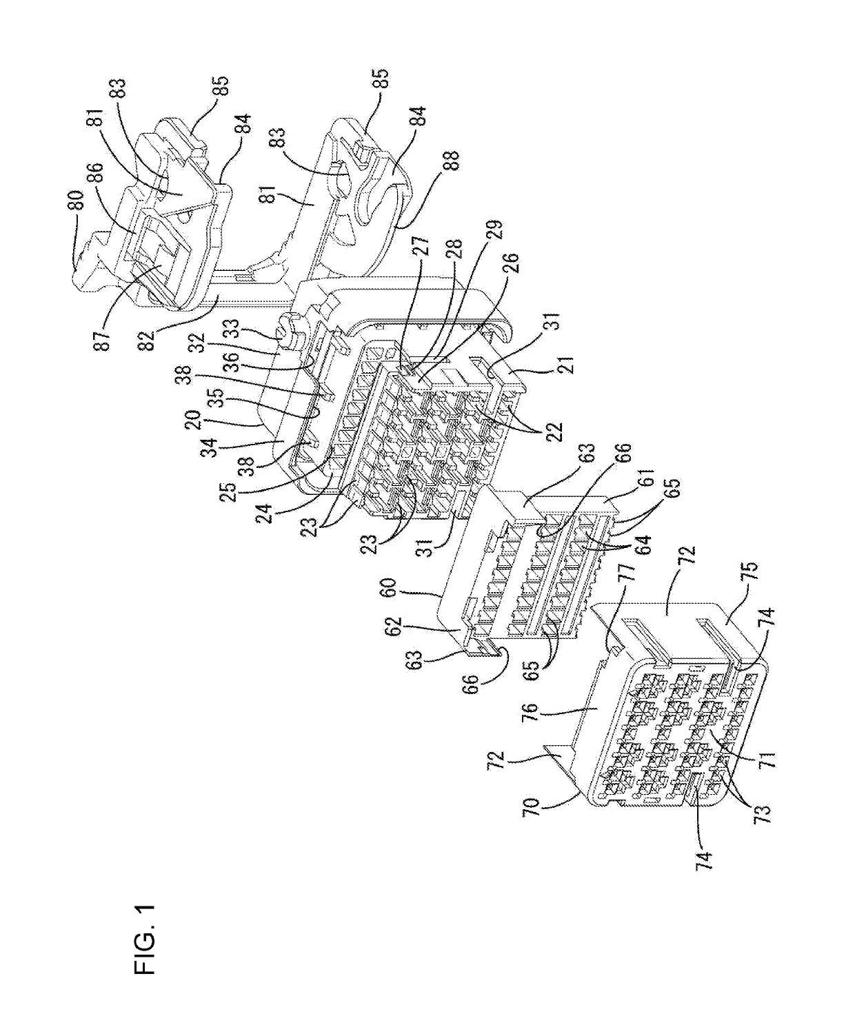
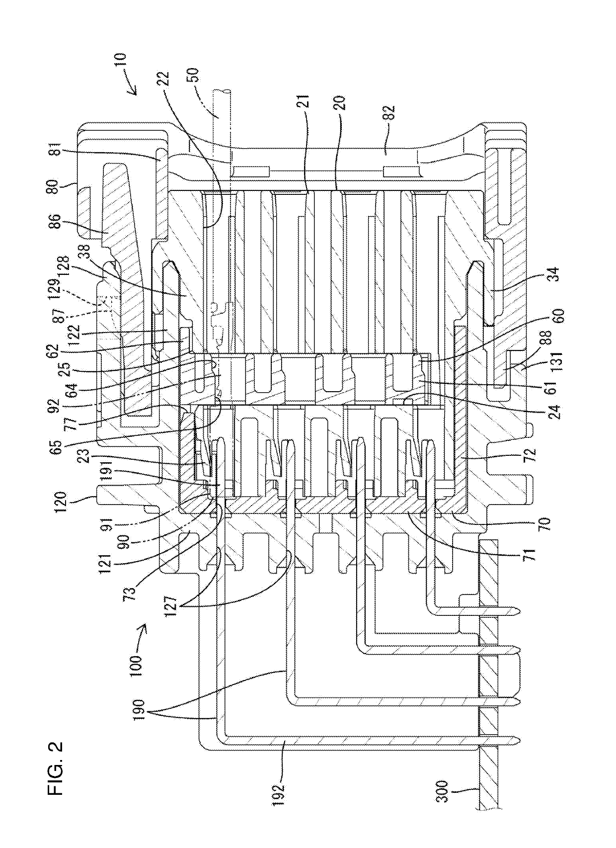
[0024]One embodiment is described with reference to the drawings. This embodiment includes a non-waterproof connector 10 and a waterproof connector 10A, and either one of the connectors 10, 10A can be selected and used according to user needs for non-waterproof specifications or waterproof specifications. A mating connector 100 serving as a connection partner has substantially the same shape for both the non-waterproof connector 10 and the waterproof connector 10A. Note that, in the following description, surfaces of the connector (non-waterproof connector 10, waterproof connector 10A) and the mating connector 100 facing each other at the start of connection are referred to as front ends.

[Mating Connector 100]

[0025]As shown in FIG. 10, the mating connector 100 includes a mating housing 120 and mating terminal fittings 190. The mating housing 120 is made of synthetic resin and includes, as shown in FIG. 2, a base 121 in the form of a back plate extending along a lateral direction and...


PUM


Abstract

Both a non-waterproof connector (10) and a waterproof connector (10A) include a housing (20, 20A) having a retainer mounting hole (24) open in an outer surface, and a retainer (60) to be inserted into the retainer mounting hole (24). In the waterproof connector (10A), a seal ring (210) is fit on a rear side of the outer surface of the housing (20A), out of both front and rear sides across an opening of the retainer mounting hole (24). In the non-waterproof connector (10), restricting portions (38) are provided to project on the rear side of the outer surface of the housing (20). The restricting portions (38) can come into contact with an inner surface on an opening side of a receptacle (122) in a fitting state.

Description

BACKGROUNDField of the Invention[0001]The invention relates to a connector and a connector structure.Related Art[0002]Japanese Unexamined Patent Publication No. 2016-91761 discloses a waterproof connector with a housing including cavities into which terminal fittings are insertable. A retainer mounting hole is open in the upper surface of the housing and communicates with each cavity. A rubber ring is to be fit on a rear side of the outer surface of the housing across the retainer mounting hole.[0003]A retainer is inserted and held in the retainer mounting hole of the housing and retains the terminal fitting in each cavity. A pressing portion of the retainer projects through the opening of the retainer mounting hole on the upper surface of the housing. The rubber ring fit on the housing is rearward of the pressing portion and functions to seal between the housing and a receptacle while suppressing rattling by resiliently contacting an inner surface on an opening side of the receptac...

Claims


Application Information

Patent Timeline
Patent Type & Authority Applications(United States)
IPC IPC(8): H01R13/436H01R13/502H01R13/629H01R13/52
CPCH01R13/4368H01R13/502H01R13/62938H01R13/5219H01R27/02H01R12/724H01R13/4364
Inventor OBATA, MASAYUKITERAMOTO, MARI
Owner SUMITOMO WIRING SYST LTD
Why Eureka
Try Eureka