
Panel light apparatus

a panel light and light fixture technology, applied in fixed installation, lighting and heating devices, lighting support devices, etc., can solve the problems of inconvenient installation or replacement of such light devices, and the difficulty of replacing such light devices, so as to simplify the installation work of the detachable panel module, reduce the overall height of the panel light apparatus, and achieve great technical results

Inactive Publication Date: 2019-05-09
XIAMEN ECO LIGHTING CO LTD
View PDF10 Cites 1 Cited by
  • Summary
  • Abstract
  • Description
  • Claims
  • Application Information

AI Technical Summary

Benefits of technology

The patent text describes a panel light apparatus with a bracket and a detachable panel module that can be easily installed and detached. The bracket has a stop structure to keep the connector in place, except for when an external force is applied to detach it. The bracket is designed in a U shape structure, which reduces the overall height of the panel light apparatus when installed to a ceiling. The bracket also includes a pluggable terminal for easy electrical connection and a driver container space for storing the driver circuit, which decreases the size and manufacturing cost of the panel light apparatus. The technical effects of the patent text include simplified installation work, increased safety standards, reduced overall size, and decreased manufacturing costs.

Problems solved by technology

For downlight devices, and panel light devices, they are usually fixed to a ceiling, which is usually very tall and cannot accessible without a ladder.
Therefore, it is inconvenient to install or to replace such light devices.
Yet, when the light devices are thinner, everything becomes more difficult.

Method used


Image

  • Panel light apparatus
  • Panel light apparatus
  • Panel light apparatus

Examples


Embodiment Construction

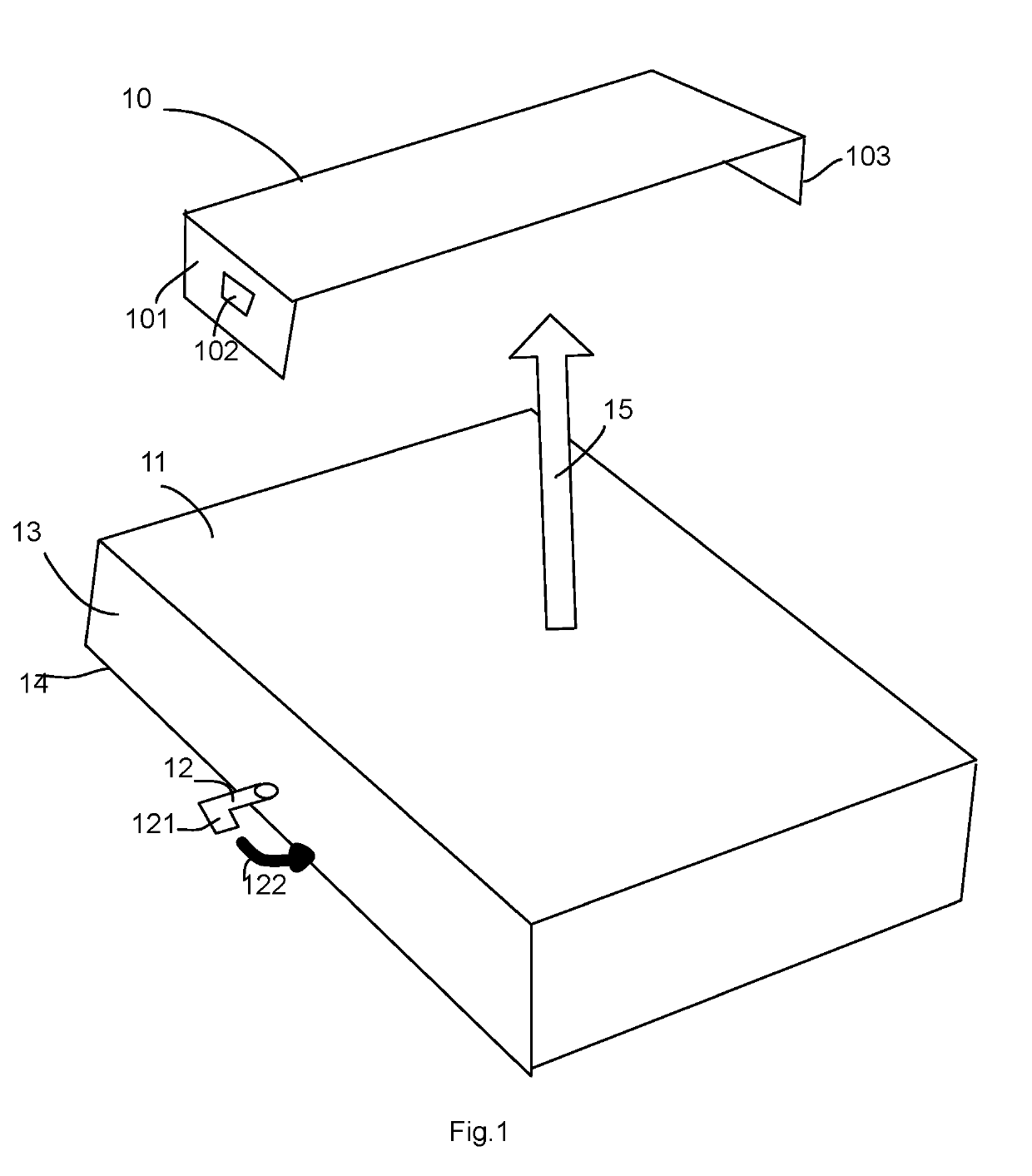
[0042]Please refer to FIG. 1. FIG. 1 illustrates an example of a bracket and a detachable panel module.

[0043]In FIG. 1, a bracket 10 has a first lateral side 101 and a second lateral side 103. In FIG. 1, it is illustrated that there is a first hole 102 in the first lateral side 101.

[0044]A detachable panel module has a back cover 11, a surrounding wall 13 and a panel 14. In addition, the detachable panel module has two connectors in the surrounding wall 13, like the first connector 12 illustrated in FIG. 1.

[0045]The detachable panel module is fixed along the direction 15 to the bracket 10. The first connector 12 has a rotation pin 121 to rotate with the rotation direction 122 to fit into the first hole 102 of the first lateral side 101 of the bracket 10 to attach the detachable panel module to the bracket 10.

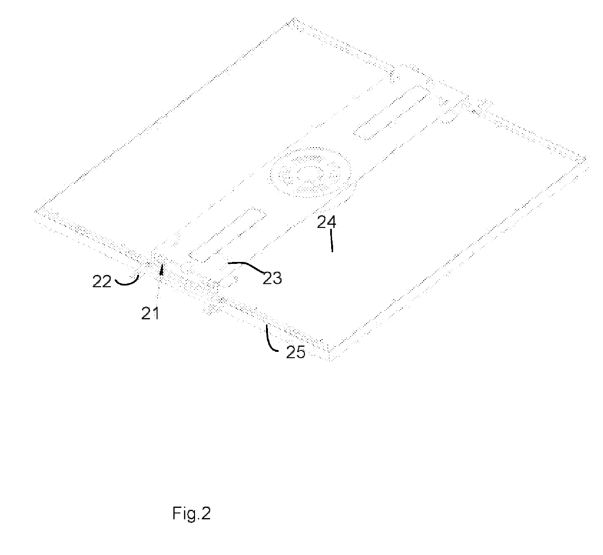
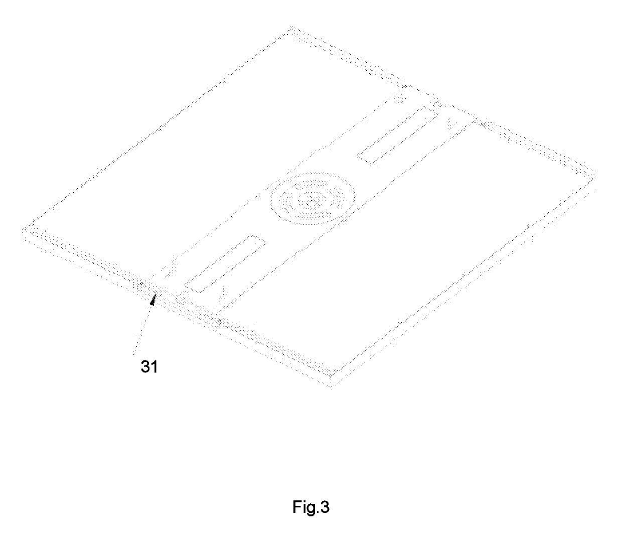
[0046]Please refer to FIG. 2 and FIG. 3. FIG. 2 is a more specific example of a panel light embodiment. FIG. 3 is another status of the embodiment of FIG. 2.

[0047]In FIG. 2 and ...


PUM


Abstract

A panel light apparatus is designed to be installed to a ceiling. The panel light apparatus has a bracket firstly fixed to the ceiling. The bracket has a first lateral side and a second lateral side. The panel light apparatus has a detachable panel module to be attached to the bracket. The detachable panel module has a panel, a surrounding wall, a back cover, a first connector and a second connector. When the detachable panel module is attached to the bracket, the first connector and the second connector respectively have insertion portions kept in holes of the first lateral side and the second lateral side of the bracket.

Description

FIELD OF INVENTION[0001]The present invention relates to a panel light apparatus and more particularly related to a panel light apparatus to be fixed to a ceiling.BACKGROUND[0002]With the new LED (Light Emitted Diode) technology, various traditional light devices now have more features, less weight, higher optical conversion rate, etc.[0003]In the field of light devices, users usually want their light devices thinner, lighter while also easy and convenient to be installed to a desired position. For downlight devices, and panel light devices, they are usually fixed to a ceiling, which is usually very tall and cannot accessible without a ladder.[0004]Therefore, it is inconvenient to install or to replace such light devices. Various structures are designed for better ways for doing such operation. Yet, when the light devices are thinner, everything becomes more difficult.[0005]Thus, it is beneficial, if a reliable connecting structure that is easy to be installed while keeping a panel ...

Claims


Application Information

Patent Timeline
Patent Type & Authority Applications(United States)
IPC IPC(8): F21S8/04F21V21/03F21S8/00
CPCF21S8/043F21V21/03F21S8/037F21Y2105/00F21Y2115/10F21V29/503F21S8/026F21V17/164F21V19/001F21V23/003F21V21/02
Inventor YE, XIAOJUNGAN, HUANGBINLEI, YI
Owner XIAMEN ECO LIGHTING CO LTD
Learn More