Supercharge Your Innovation With Domain-Expert AI Agents!

Trailer skirt and mud flap slanted inwards

a technology of mud flaps and trailer skirts, applied in the direction of vehicle components, vehicle body streamlining, superstructure subunits, etc., can solve the problems of reducing propulsive efficiency, energy loss, uneven distribution of frictional drag forces, etc., and achieve the effect of reducing the required effective vehicle propulsive counterforce and reducing the total drag-induced resistive forces

Inactive Publication Date: 2019-05-16
MAGEE GARTH L
View PDF13 Cites 3 Cited by
  • Summary
  • Abstract
  • Description
  • Claims
  • Application Information

AI Technical Summary

Benefits of technology

The patent is about a device that reduces the drag and increases the efficiency of vehicles with wind-exposed wheels, such as trailers of commercial trucks. The device includes wind-diverting skirts or panels that deflect the headwinds onto the lower wheels, which are the least aerodynamic. This reduces the drag on the wheels and increases the vehicle's propulsive efficiency. The device also keeps the lower wheel surfaces exposed to headwinds, which further improves efficiency. Another embodiment of the device includes an inwardly slanting aerodynamic trailer skirt or mud flap that induces air flow and reduces pressure drag between the front and back of the vehicle, resulting in a overall reduction in vehicle drag.

Problems solved by technology

Inherently characteristic of rotating vehicle wheels, and particularly of spoked wheels, aerodynamic resistance, or parasitic drag, is an unwanted source of energy loss in propelling a vehicle.
However, as will be shown, frictional drag forces are not uniformly distributed with elevation on the wheel, as they are not uniformly related to the speed of the moving outline of the wheel rim.
Vehicles having wind-exposed wheels are particularly sensitive to external headwinds reducing propulsive efficiency.
Such propulsive counterforces suffer a mechanical disadvantage against the upper wheel drag forces, since each net force is applied about the same pivot point located at the bottom where the wheel is in stationary contact with the ground.
Furthermore, shielding the lower wheel surfaces can cause a net increase in vehicle drag, and a loss in propulsive efficiency.
As a result, aerodynamic trailer skirts in widespread use today are unnecessarily inefficient, since they generally extend below the level of the axle.
Nevertheless, extended height trailer skirts have been shown to improve propulsive efficiency, since they reduce the aerodynamic pressure on the upper wheel surfaces, which cause the vast majority of wheel drag and virtually all of the loss in vehicle propulsive efficiency due to wheel drag.
As mentioned, diverting wind from impinging on the lower wheel surfaces actually increases overall vehicle drag, reducing propulsive efficiency.
Deflecting wind from impinging on these lower wheel surfaces transfers the aerodynamic pressure from these slower moving surfaces also suffering a mechanical disadvantage, to faster moving vehicle body surfaces having no mechanical advantage over propulsive counterforces, thereby increasing vehicle drag.
Due to the nonlinear effects of upper wheel drag in rising headwinds, such techniques can produce inaccurate measurements of gains in propulsive efficiency for vehicles having wheels exposed to headwinds.
Thus, as yet this important relationship of upper wheel drag more predominately affecting overall vehicle drag—and especially over lower wheel drag which is often comparatively negligible and suffers a mechanical disadvantage against propulsive counterforces applied at the axle—has gone unrecognized.
For example, the oscillating system in U.S. Pat. No. 9,487,250—intended to reduce pressure drag on the vehicle itself—introduces considerable complexity over more common fixed drag-reduction means, since it generally includes a moving diaphragm that must be tuned for the specific operating configuration of the vehicle.
However, more recent configurations include the forwardmost ends thereof being disposed slightly inset toward the longitudinal centerline of the vehicle body, since it has been found through testing that this outwardly slanted configuration further decreases overall vehicle drag.
As such, skilled artisans have had no motivation to consider a contrary arrangement further exposing the rearward wheels to headwinds, since such a contrary arrangement would be known to substantially increase drag on the vehicle.
As such, it has remained unappreciated in the art that any increased drag induced on these undercarriage components could be insufficient to offset the overall drag reduction gains achievable simply by instead redirecting substantial air flow in-between the trailer wheel sets to thereby substantially reduce pressure drag on the vehicle.
And such, these lengthy air ducts have substantial surface areas, introducing considerable friction drag thereon—on surfaces thereof both within and without the duct itself—to thereby limit any reduction in overall vehicle drag gained from any reduction in pressure drag on the vehicle itself.
And in U.S. Pat. No. 9,403,563 much smaller air ducts were used on the rear of the trailer, which still introduce considerable friction drag for their relatively small size, especially when considering that the their smaller size severely limits the potential amount of redirected air, thereby further limiting their effectiveness in increasing the effective pressure developed in the relatively large volume of reduced pressure zone located immediately behind the trailer.
Thus, these smaller air ducts redirecting smaller volumes of air also have limited potential to reduce the overall pressure drag on the vehicle.

Method used


Image

  • Trailer skirt and mud flap slanted inwards
  • Trailer skirt and mud flap slanted inwards
  • Trailer skirt and mud flap slanted inwards

Examples


first embodiment

nd 2

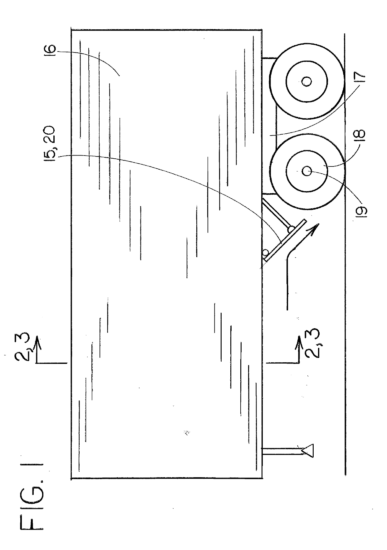
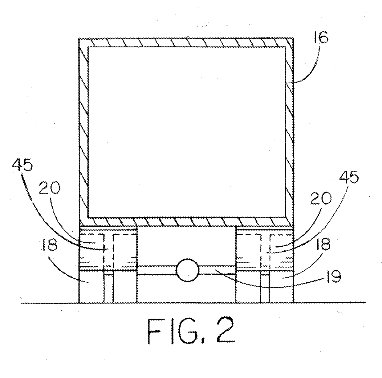
[0102]As shown in FIGS. 1 and 2, an embodiment comprises an inclined aerodynamic wheel deflector panel assembly 20 attached to and mounted underneath the body of a trailer 16 for a commercial vehicle. The inclined wheel deflector panel assembly 20 is located forward of the rear wheel assembly 17 and located directly in front of a trailing wheel set 18 which would otherwise be exposed to headwinds when the vehicle is in forward motion. The inclined wheel deflector panel assembly 20 is planar in shape, mounted inclined in a forwardly-angled orientation with the upper edge more forwardly located and the lower surface located more rearward on the vehicle. The inclined wheel deflector panel assembly 20 spans the lateral width of the trailing wheel set 18 of the trailing rear wheel assembly 17 located on either side of the vehicle. The optimal inclined wheel deflector panel assembly 20 extends downward ideally to no lower than the level of the axle 19 and is located proximal to the tr...

second embodiment

d 3

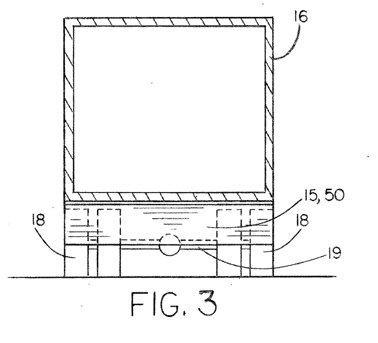
[0125]As shown in FIGS. 1 and 3, an embodiment comprises an inclined aerodynamic deflector panel assembly 15 attached to and mounted underneath the body of a trailer 16 for a commercial vehicle. The inclined deflector panel assembly 15 is located forward of the rear wheel assembly 17 and located in front of trailing wheel sets 18 which would otherwise be exposed to headwinds when the vehicle is in forward motion. The inclined deflector panel assembly 15 is planar in shape, mounted inclined in a forwardly-angled orientation with the upper edge more forwardly located and the lower surface located more rearward on the vehicle. The inclined deflector panel assembly 15 spans the lateral width of the trailer 17, and where aligned directly in front of the wheel sets 18 ideally extends downward to no lower than the level of the axle. The inclined deflector panel assembly 15 is located proximal to the trailing wheel assembly 18 in order to deflect headwinds onto the exposed lower wheel su...

third embodiment

nd 5

[0126]As shown in FIGS. 4 and 5, an embodiment comprises a channeled aerodynamic wheel deflector panel assembly 25 attached to and mounted underneath the body of a trailer 16 for a commercial vehicle. The channeled wheel deflector panel assembly 25 is located forward of the rear wheel assembly 17 and located directly in front of a trailing wheel set 18 which would otherwise be exposed to headwinds when the vehicle is in forward motion. The channeled wheel deflector panel assembly 25 includes a deflector plate 22 which is generally planar in shape, mounted inclined in a forwardly-angled orientation with the upper edge more forwardly-located and the lower surface located more rearward on the vehicle. The channeled wheel deflector panel assembly 25 includes forwardly-projecting end plates 24 attached to either side edge of the deflector plate 22, forming a channeled deflector panel assembly 25 to funnel headwinds directly onto the lower wheel surfaces, minimizing any outwardly defl...


PUM


Abstract

An inwardly slanting aerodynamic trailer skirt disposed underneath a semitrailer, induces air to flow laterally inward underneath the trailer body to increase air flow in-between the trailing wheel sets, thereby causing increased air pressure to be developed immediately behind the trailer to yield a reduction in overall vehicle drag. An inwardly slanting mud flap disposed underneath a semitrailer, induces air to flow laterally inward underneath the trailer body to yield a reduction in overall vehicle drag.

Description

BACKGROUNDField[0001]The present embodiment relates to an apparatus for the reduction of aerodynamic drag on vehicles having wind-exposed wheels of a wheel assembly mounted underneath the vehicle body, such as on large commercial trucks.Description of Prior Art[0002]Inherently characteristic of rotating vehicle wheels, and particularly of spoked wheels, aerodynamic resistance, or parasitic drag, is an unwanted source of energy loss in propelling a vehicle. Parasitic drag on a wheel includes viscous drag components of form (or pressure) drag and frictional drag. Form drag on a wheel generally arises from the circular profile of a wheel moving though air at the velocity of the vehicle. The displacement of air around a moving object creates a difference in pressure between the forward and trailing surfaces, resulting in a drag force that is highly dependent on the relative wind speed acting thereon. Streamlining the wheel surfaces can reduce the pressure differential, reducing form dra...

Claims


Application Information

Patent Timeline
Patent Type & Authority Applications(United States)
IPC IPC(8): B62D35/00B62D35/02B62D25/18
CPCB62D35/001B62D35/02B62D25/188B62D25/168Y02T10/88
Inventor MAGEE, GARTH L.
Owner MAGEE GARTH L
Features
  • R&D
  • Intellectual Property
  • Life Sciences
  • Materials
  • Tech Scout
  • Unparalleled Data Quality
  • Higher Quality Content
  • 60% Fewer Hallucinations
Learn More