

METHOD and APPARATUS for MINIMIZING DRAG-INDUCED FORCES on a WHEELED VEHICLE
a technology of minimizing drag and reducing friction, which is applied in the direction of disc wheels, air-flow influencers, tyre tread bands/patterns, etc., can solve the problems of large drag, uneven distribution of frictional drag forces, and motion of wheel spokes through air, so as to reduce the incidence of trapping stones, reduce the stress of tire compression, and reduce the impact of frictional drag
- Summary
- Abstract
- Description
- Claims
- Application Information
AI Technical Summary
Benefits of technology
Problems solved by technology
Method used
Image

Examples
first embodiment
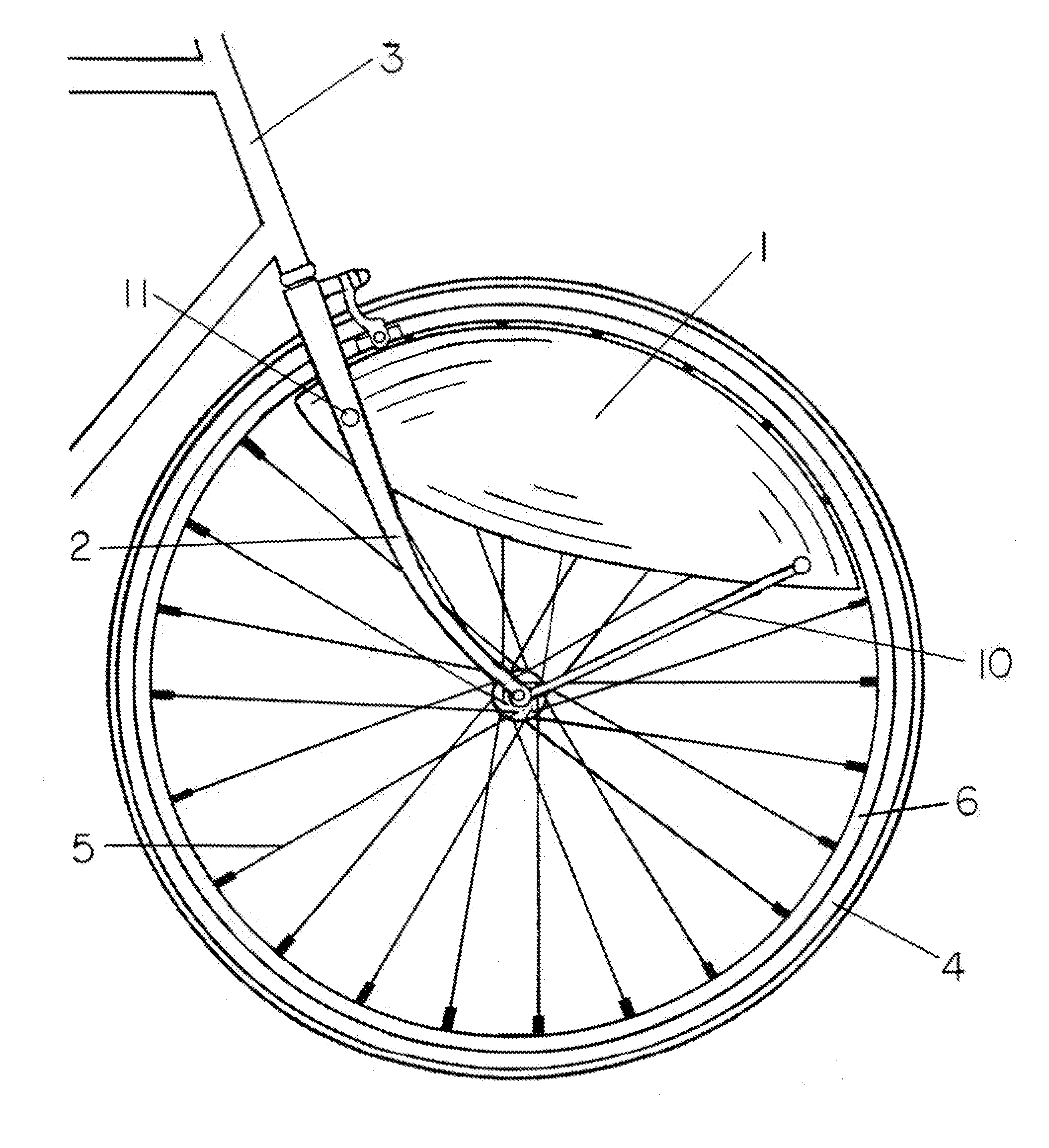
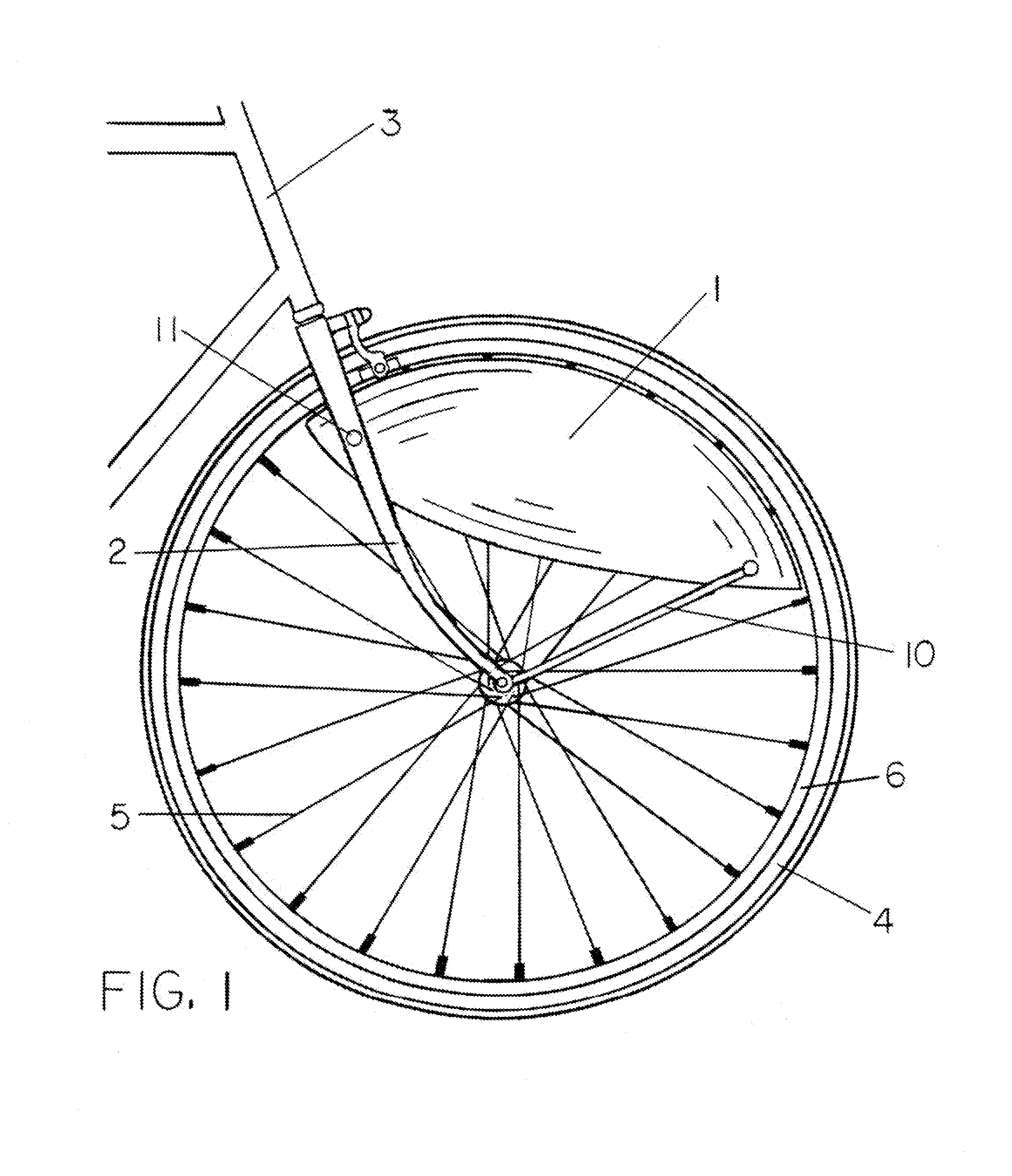
Operation—FIGS. 1, 17, 18, 23 and 24
[0084]The shielding provided by fairing 1 is particularly effective since aerodynamic forces exerted upon exposed vehicle surfaces are generally proportional to the square of the effective wind speed impinging thereon. Moreover, the power required to overcome these drag forces is generally proportional to the cube of the effective wind speed. Thus, it can be shown that the additional power required to overcome these drag forces in propelling a vehicle twice as fast over a fixed distance, in half the time, increases by a factor of eight. And since this power requirement is analogous to rider effort—in the case of a bicycle rider—it becomes critical to shield the most critical drag-inducing surfaces on a vehicle from oncoming headwinds.
[0085]In any wheel used on a vehicle, and in the absence of any external headwinds, the effective horizontal wind speed at a point on the wheel at the height of the axle is equal to the ground speed of the vehicle. In...
second embodiment
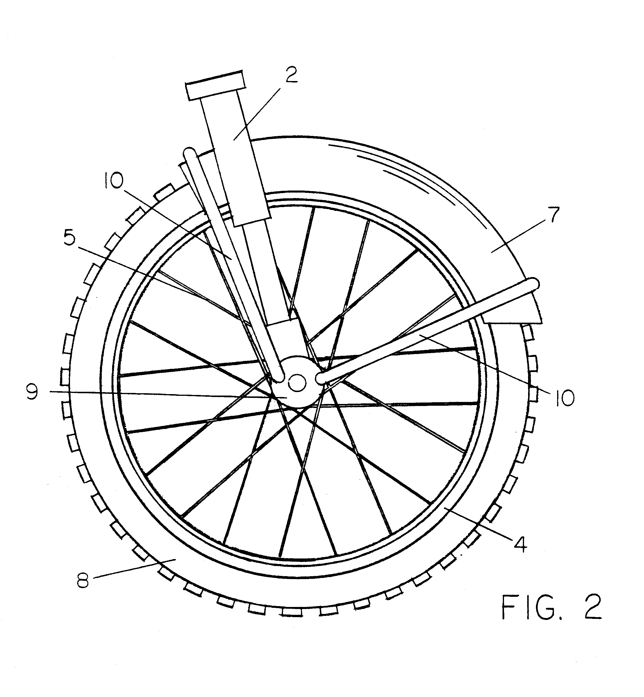
Operation—FIG. 2
[0126]An embodiment including a forwardly oriented fender 7, shielding the uppermost outer surfaces of the tire 8 from oncoming headwinds, can offer not only similar aerodynamic benefits to fairing 1 of FIG. 1 in reducing frictional drag forces on tire surfaces, but can also substantially reduce form drag forces on the wheel's forwardly facing profiles.
[0127]As discussed above, both frictional and pressure drag forces can be shown to exert moments of force pivoting about the point of ground contact. And these forces are magnified against the propulsive force required at the axle. And as such, either type of drag force exerted upon the upper wheel retards vehicle motion considerably more than a similar force exerted either upon a lower surface of the wheel, or directly upon the frame or body of the vehicle. Minimizing these upper wheel drag forces is therefore critical to improving propulsive efficiency of the vehicle.
[0128]Fender 7 is an effective means to minimize b...
third embodiment
FIG. 3
[0130]Similarly, as shown in FIG. 3, a streamlined combination fender and fairing assembly 12 is attached to the inside of front fork tube assembly 2 of a typical cycle having spoked wheels 4. The fender portion of the combination assembly 12 is positioned closely adjacent to the tire 8 covering the approximate upper and front-most quadrant of the tire 8. The fairing portions of the combination assembly 12 are positioned closely adjacent to the inner wheel structure of wheel 4 covering the approximate upper and front-most quadrant on each side of wheel 4. The combination assembly 12 is provided sufficient structural rigidity to allow close placement to wheel 4 and tire 8, thereby minimizing any oncoming headwinds from leaking either between tire 8 and the fender portion of the combination assembly 12, or between the inner structure of wheel 4 and the fairing portions of the combination assembly 12.
[0131]With the combination fender and fairing assembly 12 configured in this way...
PUM
| Property | Measurement | Unit |
|---|---|---|
| resistive forces | aaaaa | aaaaa |
| diameter | aaaaa | aaaaa |
| forces | aaaaa | aaaaa |
Abstract
Description
Claims
Application Information