Inner Circumferential Length Measurement Method for Circular Member

a technology measurement method, which is applied in the direction of measuring circumference, measuring devices, instruments, etc., can solve the problems of inconvenient improvement of inner circumferential length of circular members, affecting the accuracy of inner circumferential length measurement, and affecting the quality of rubber products manufactured using circular members. achieve the effect of high accuracy

Active Publication Date: 2019-05-23
THE YOKOHAMA RUBBER CO LTD
View PDF6 Cites 4 Cited by
  • Summary
  • Abstract
  • Description
  • Claims
  • Application Information

AI Technical Summary

Benefits of technology

[0005]The present technology is to provide an inner circumferential length measurement method for a circular member capable of accurately measuring an inner circumferential length without applying an unnecessary load of the circular member.
[0011]According to an embodiment of the present technology, the inner circumferential length of the circular member placed flat in an unrestrained state on the support is measured using the two-dimensional sensor without the two-dimensional sensor coming into contact with the circular member. Thus, an unnecessary load is not applied to the circular member, and thus deformation thought obligatory does not occur. This is advantageous in measuring the inner circumferential length of the circular member with high accuracy.

Problems solved by technology

However, due to a manufacturing error or the like, the actual inner circumferential length of the circular member may differ from the preset setting value.
However, in a case where this deviation is outside of this tolerance range, the rubber product manufactured using the circular member may have quality problems.
This may cause deformation.
Thus, this is not advantageous in improving the accuracy in measuring the inner circumferential length.
However, because the roller directly comes into contact and pushes against the inner circumferential surface of the bead member, deformation may occur.
Thus, this is not advantageous in improving the accuracy in measuring the inner circumferential length.

Method used


Image

  • Inner Circumferential Length Measurement Method for Circular Member
  • Inner Circumferential Length Measurement Method for Circular Member
  • Inner Circumferential Length Measurement Method for Circular Member

Examples


Embodiment Construction

[0018]An inner circumferential length measurement method for a circular member according to embodiments of the present technology will be described in detail below with reference to embodiments illustrated in the drawings.

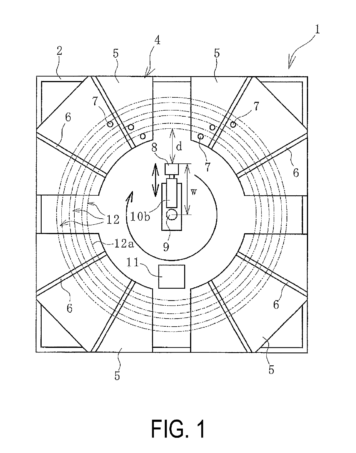
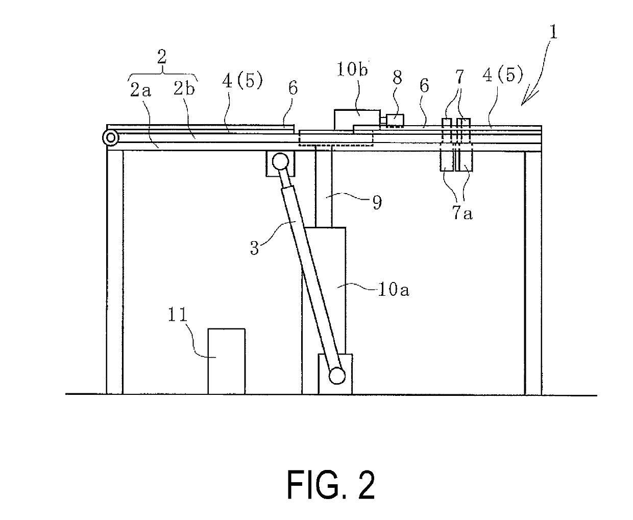
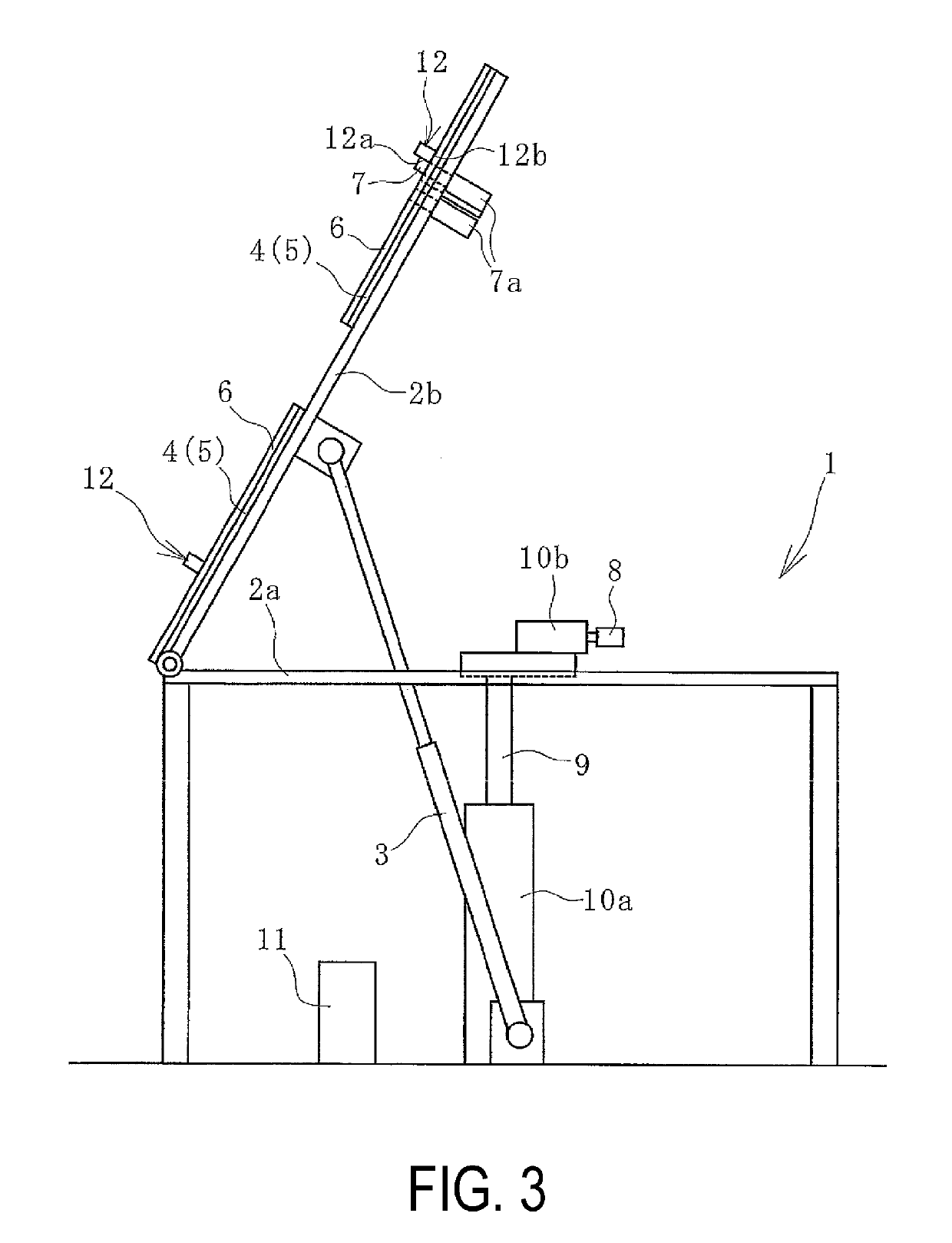
[0019]An inner circumferential length measurement method for a circular member according to an embodiment of the present technology uses an inner circumferential length measuring device 1 (referred to as measuring device 1 below) for a circular member illustrated in FIGS. 1 and 2. In an embodiment of the present technology, the inner circumferential length can be measured for various circular members 12 (circular members and annular members) such as bead members and cylindrical rubber members used in a rubber product such as a tire. In FIG. 1, the circular member 12 is indicated by a two-dot chain line. When measuring, a single circular member 12 is set in the measuring device 1.

[0020]The measuring device 1 includes a support 4 on which the circular member 12 to be...


PUM


Abstract

An inner circumferential length measurement method includes the steps of: disposing a two-dimensional sensor at a predetermined measurement position on an inner side of the circular member placed flat in an unrestrained state on a support so that the two-dimensional sensor faces an inner circumferential surface of the circular member in a non-contact state; rotating the two-dimensional sensor about rotation shaft at a predetermined position on the inner side of the circular member; measuring a separation distance from the two-dimensional sensor to the inner circumferential surface around an entire circumference of the circular member; and calculating an inner circumferential length of the circular member via a calculation unit using the separation distance measured and a distance from the rotation shaft to the two-dimensional sensor in a plan view.

Description

TECHNICAL FIELD[0001]The present technology relates an inner circumferential length measurement method for a circular member and particularly relates to an inner circumferential length measurement method for a circular member capable of accurately measuring an inner circumferential length without applying an unnecessary load on the circular member.BACKGROUND ART[0002]Various circular members (circular members and annular members) such as bead members and cylindrical rubber members are used in the manufacture of a rubber product such as a tire. The inner circumferential length of such a circular member has a preset setting value designated by the design. However, due to a manufacturing error or the like, the actual inner circumferential length of the circular member may differ from the preset setting value. In a case where this deviation is within a tolerance range, there is no problem. However, in a case where this deviation is outside of this tolerance range, the rubber product man...

Claims


Application Information

Patent Timeline
Patent Type & Authority Applications(United States)
IPC IPC(8): G01B11/04G01B21/06G01B11/02
CPCG01B11/043G01B21/06G01B11/026G01B11/02G01B5/025G01B11/12G01B21/02
Inventor MATSUMURA, KENSUKESUGIYAMA, YUICHI
Owner THE YOKOHAMA RUBBER CO LTD
Why Eureka
Try Eureka