Radio-location method for locating a target device contained within a region of space

a radio-location method and target device technology, applied in the direction of location information based service, transmission monitoring, instruments, etc., can solve the problems of propagation of inaccurate or unknown location estimates, inability to easily eliminate anomalies, and inability to accurately determine the location of the target devi

Active Publication Date: 2019-05-23
KK TOSHIBA
View PDF8 Cites 10 Cited by
  • Summary
  • Abstract
  • Description
  • Claims
  • Application Information

AI Technical Summary

Problems solved by technology

However, the presence of propagation anomalies such as multi-path reflection, interference and shadowing can result in spurious location candidates.
These anomalies cannot be easily eliminated if they appear equally likely to be valid.
In addition, some measurements may have unknown or inaccurate reference location estimates.
Hence, the multi-lateration or intersections will also result in the propagation of the inaccurate or unknown location estimates.

Method used

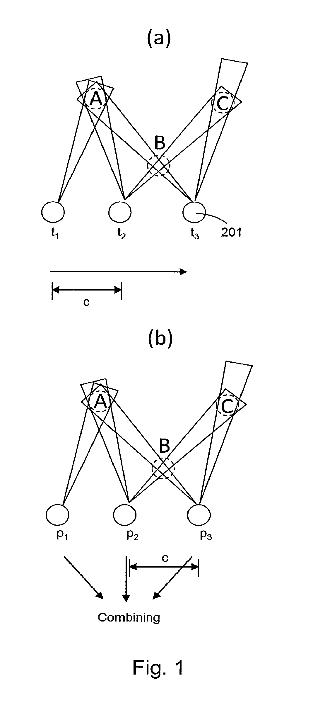
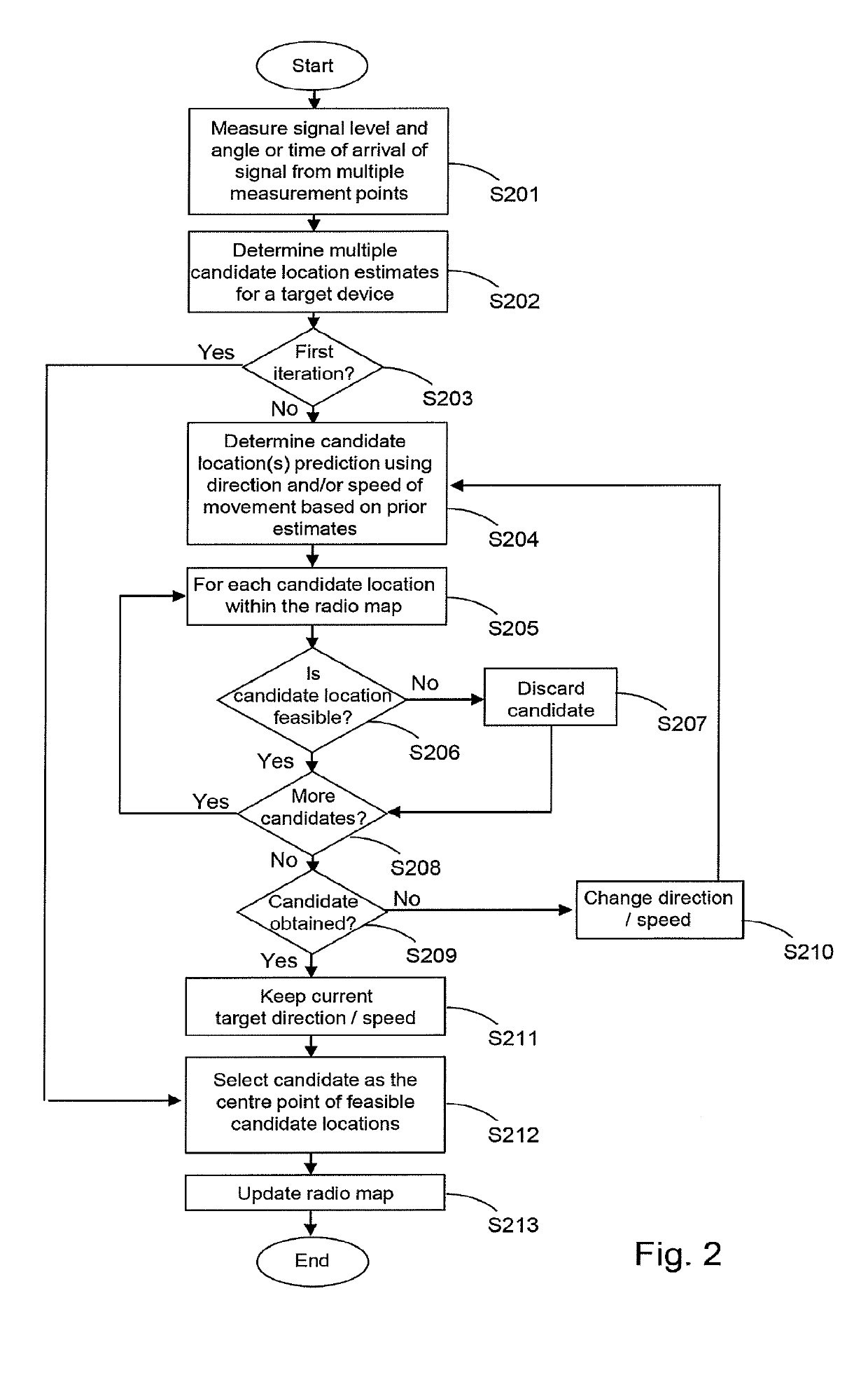
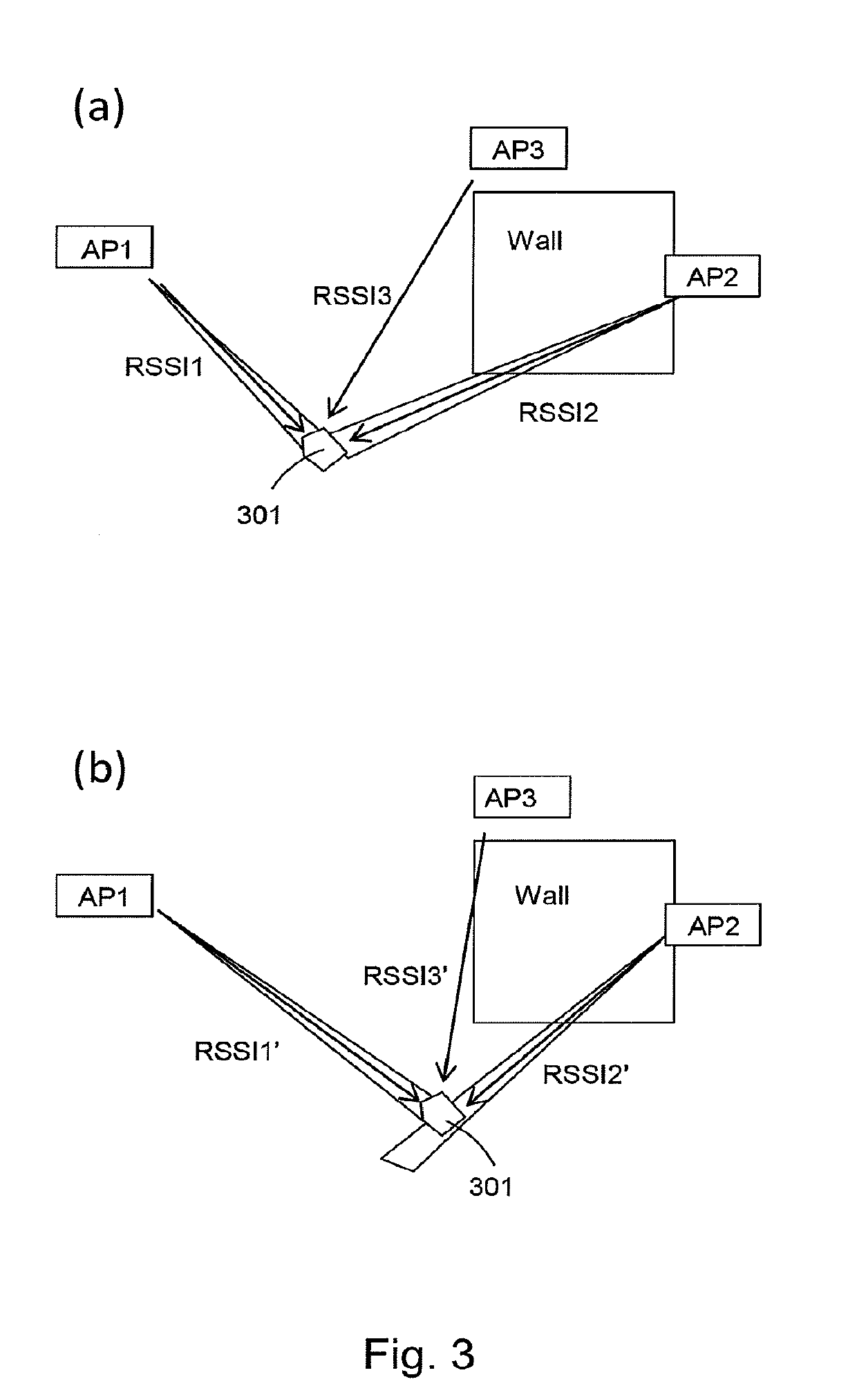

Image

  • Radio-location method for locating a target device contained within a region of space
  • Radio-location method for locating a target device contained within a region of space
  • Radio-location method for locating a target device contained within a region of space

Examples


first embodiment

[0012] there is provided a radio-location method of locating a target device that is contained within a region of space, the method comprising:[0013]obtaining a first set of detected signals by detecting, by one or more detectors at a plurality of points in space, a beacon signal from the target device, or by detecting at the target device, beacon signals sent from one or more radio transmitters in the region of space;[0014]determining, based on the characteristics of the first set of detected signals, a current estimate of the target device's location;[0015]obtaining successive sets of detected signals, each set of detected signals being obtained by detecting, at the one or more detectors, a beacon signal from the target device, or by detecting at the target device, beacon signals sent from the one or more radio transmitters;[0016]for each successive set of detected signals:[0017]retrieving the current estimate of the target device's location;[0018]determining, based on characteris...

third embodiment

[0027] there is provided a radio-location method of locating a target device that is contained within a region of space, the method comprising:[0028]obtaining a first set of detected signals by detecting, by one or more detectors at a plurality of points in space, a beacon signal from the target device, or by detecting at the target device, beacon signals sent from one or more radio transmitters in the region of space;[0029]determining, based on the characteristics of the first set of detected signals, a current estimate of the target device's location; and[0030]for each of one or more iterations:[0031]predicting, based at least in part on the current estimate of the target device's location, one or more new candidate locations for the target device;[0032]comparing the candidate locations with a radio map of the region of space, the radio map identifying obstructions to radio wave propagation contained within the region of space;[0033]identifying, from the one or more candidate loca...


PUM


Abstract

A radio-location method of locating a target device that is contained within a region of space, comprising obtaining a first set of detected signals by detecting, at a plurality of points in space, a beacon signal from the target device, or by detecting at the target device, beacon signals sent from one or more radio transmitters in the region of space; determining a current estimate of the target device's location; obtaining successive sets of detected signals, for each successive set of detected signals: determining one or more candidate locations for the target device; comparing the candidate locations with a radio map of the region of space, identifying one or more feasible candidate locations that are consistent with the radio map; determining a new estimate of the target device's location based on the one or more feasible candidate locations; and setting the new estimate as the current estimate of the target device's location.

Description

TECHNICAL FIELD[0001]Embodiments described herein relate to a radio-location method for locating a target device contained within a region of space.BACKGROUND[0002]Radiolocation is an established technique for determining the location of a target device. The target is provided with a radio tag that will transmit beacon signals to one or more remote detectors, or alternatively receive beacon signals from one or more remote radio transmitters, at periodic intervals. By detecting the beacons signals, it is possible to infer information about the target location.[0003]Conventional radiolocation methods exploit measurements of the angle of arrival (AoA) or time of arrival (ToA) or perform a multi-lateration or intersection test (such as triangulation) to compute the most likely location of the target. The most likely candidate location then has to be selected by a selection process which can consider the prediction of the likely movement of the target from prior estimates. However, the p...

Claims


Application Information

Patent Timeline
Patent Type & Authority Applications(United States)
IPC IPC(8): H04W4/02H04W64/00H04B17/318G01S5/02
CPCH04W4/025H04W64/003H04B17/318G01S5/0252G01S5/0242G01S5/0284G01S5/02524G01S5/02585
Inventor FARNHAM, TIMOTHY DAVID
Owner KK TOSHIBA
Why Eureka
Try Eureka