
Method for selecting one of a plurality of radio interfaces of a mobile radio telecommunication terminal

a radio interface technology, applied in the field of mobile radio telecommunication terminals, can solve problems such as inability to correct the doppler effect, and achieve the effect of saving energy and efficiently assigning radio services the resources available for data transmission and reception

Inactive Publication Date: 2010-11-30
ALCATEL LUCENT SAS
View PDF11 Cites 6 Cited by
  • Summary
  • Abstract
  • Description
  • Claims
  • Application Information

AI Technical Summary

Benefits of technology

The present invention is a mobile radio telecommunication terminal that allows for efficient detection and connection to available sub-radio access networks, while saving energy and resources. The terminal detects the presence of available networks only when necessary, such as when higher bandwidth is needed for a particular service or when the current network environment offers poor mobility features. The terminal selects the appropriate network based on the desired bandwidth and other factors such as quality of service, handover, and security. This results in a more efficient use of available network resources and better user experience. The terminal also allows for seamless handover and shorter data interruption during handover. Overall, the invention improves the efficiency and flexibility of mobile radio communication.

Problems solved by technology

However, in average the network environment is scanned less often than in the known telecommunication terminals and, therefore, works very energy efficient.
Depending on the transmission technique used for the radio connection, there is a certain speed limit, above which a Doppler effect may occur which cannot be corrected.

Method used

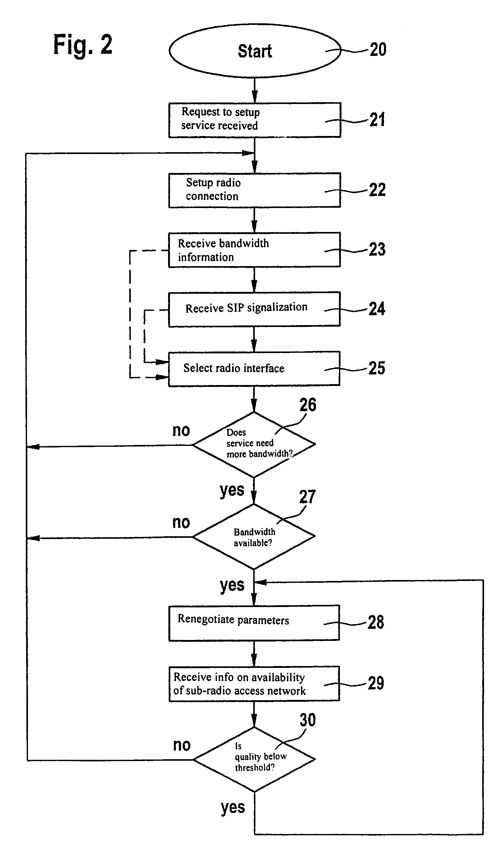

Image

  • Method for selecting one of a plurality of radio interfaces of a mobile radio telecommunication terminal
  • Method for selecting one of a plurality of radio interfaces of a mobile radio telecommunication terminal
  • Method for selecting one of a plurality of radio interfaces of a mobile radio telecommunication terminal

Examples


Embodiment Construction

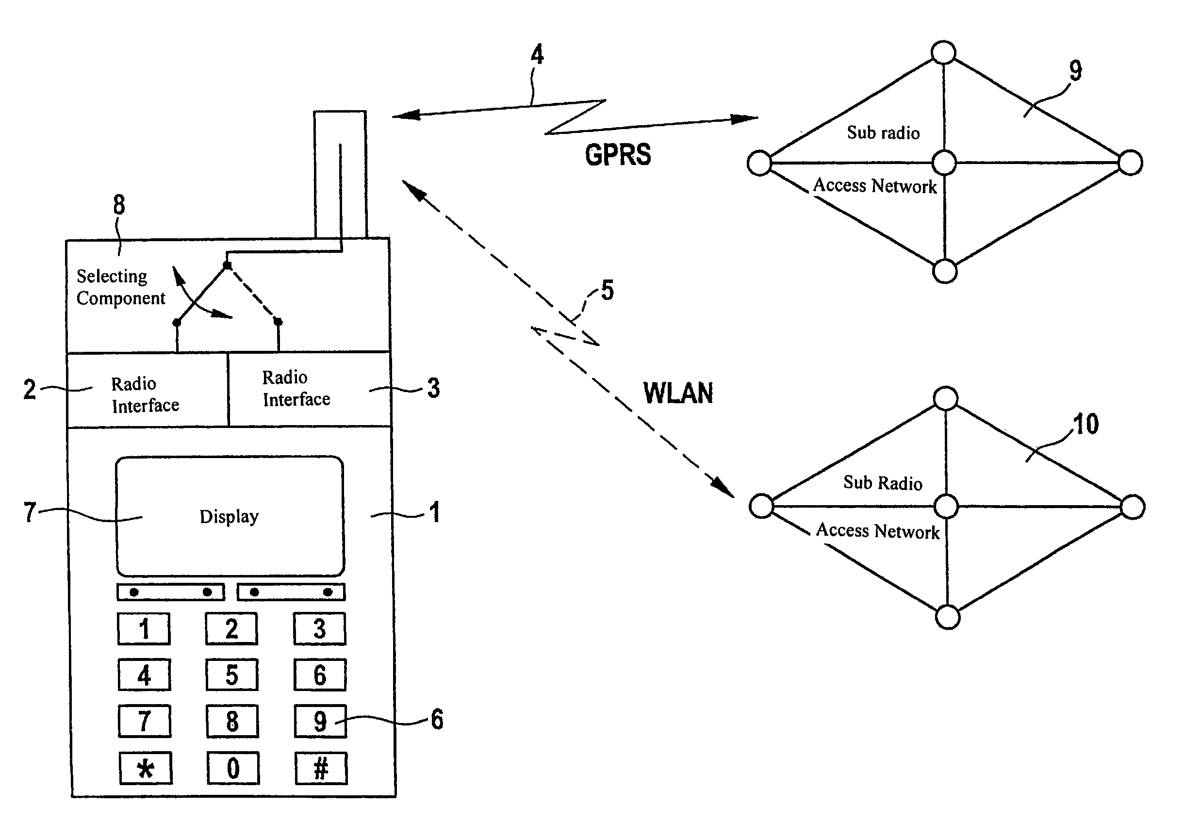
[0028]In FIG. 1 a mobile radio telecommunication terminal is designated with reference sign 1. The telecommunication terminal 1 is a mobile phone. Of course, the telecommunication terminal 1 could be a smart phone or any kind of computer (palmtop, PDA (Personal Digital Assistant) or personal computer) equipped with the appropriate hardware and software for effecting data transmission and data reception according to a certain radio protocol, too. The telecommunication terminal 1 comprises two radio interfaces 2, 3 dedicated for transmitting and receiving data across radio connections 4, 5 according to different radio protocols. For example, radio interface 2 is dedicated for transmitting and receiving data across the radio connection 4 according to a GPRS-protocol. The other radio interface 3 is dedicated for transmitting and receiving data across the second radio connection 5 according to a WLAN-protocol.

[0029]Furthermore, the telecommunication terminal 1 comprises input means 6 whi...


PUM


Abstract

The invention refers to a method for establishing a radio connection (4, 5) for transmitting and receiving data across one of a plurality of radio interfaces (2, 3) of a mobile radio telecommunication terminal (1). The multiple radio interfaces (2, 3) serve for data transmission and reception across radio connections (4, 5) according to various radio protocols within different sub-radio access networks (9, 10). The coverage of sub-radio access networks (9, 10) is determined and the radio connection (4, 5) is established across at least one of the available sub-radio access networks (9, 10). In order to establish a radio connection (4, 5) for transmitting and receiving data across one of the plurality of radio interfaces (2, 3) of the mobile radio telecommunication terminal (1) more efficiently without waste of energy and waste of bandwidth on the radio connections (4, 5) the necessity for a determination of sub-radio access network (9, 10) coverage is established and coverage of the sub-radio access networks (9, 10) is determined only if determination of sub-radio access network (9, 10) coverage is deemed to be necessary.

Description

[0001]The invention is based on a priority application EP 03 291 720.5 which is hereby incorporated by reference.FIELD OF THE INVENTION[0002]The present invention refers to a mobile radio telecommunication terminal comprising multiple radio interfaces dedicated for transmitting and receiving data across radio connections according to various radio protocols. The telecommunication terminal further comprises means for detecting sub-radio access networks dedicated for transmitting and receiving data according to the various radio protocols. Furthermore, the telecommunication terminal comprises means for connecting to at least one of the available sub-radio access networks thereby establishing at least one radio connection.[0003]Further, the present invention refers to a method for establishing a radio connection for transmitting and receiving data across one of a plurality of radio interfaces of a mobile radio telecommunication terminal. The multiple radio interfaces serve for data tra...

Claims


Application Information

Patent Timeline
Patent Type & Authority Patents(United States)
IPC IPC(8): H04W36/00H04W4/00H04L12/28H04L12/56H04W48/16H04W52/02H04W88/06
CPCH04W48/16H04W88/06H04W52/0229Y02B60/50Y02D30/70
Inventor ROUFFET, DENISMAILLARD, HERVE
Owner ALCATEL LUCENT SAS
Learn More