Radio communication system, radio station, and method for controlling transmission power

a radio communication system and radio station technology, applied in power management, radio transmission, electrical equipment, etc., can solve problems such as inter-cell interference and decrease in communication rates of terminals in that cell, and achieve the effect of improving user throughput fairness

Active Publication Date: 2015-12-10
NEC CORP
View PDF3 Cites 7 Cited by
  • Summary
  • Abstract
  • Description
  • Claims
  • Application Information

AI Technical Summary

Benefits of technology

[0020]According to the present invention, the transmission power of a radio terminal connected to the radio area of an own station is controlled based on the relative magnitude of a load on the own station to

Problems solved by technology

Accordingly, inter-cell interference may occur when neighbor cells use the same frequency band for transmission, regardless of uplink transmission or downlink transmission.
In a heterogeneous network in particular, the problem of load balancing is also among concerns, in addition to the problem of interference caused along with the i

Method used


Image

  • Radio communication system, radio station, and method for controlling transmission power
  • Radio communication system, radio station, and method for controlling transmission power
  • Radio communication system, radio station, and method for controlling transmission power

Examples


first example

3.1) First Example

[0044]According to a first example of the present invention, a PRB usage is used as a load; a load difference is used as a relative load; common target received power Po_No_Pusch (PO—NOMINAL—PUSCH) is used as a transmission power adjustment parameter; and fixed values are used for adjusting transmission power, which will be described next.

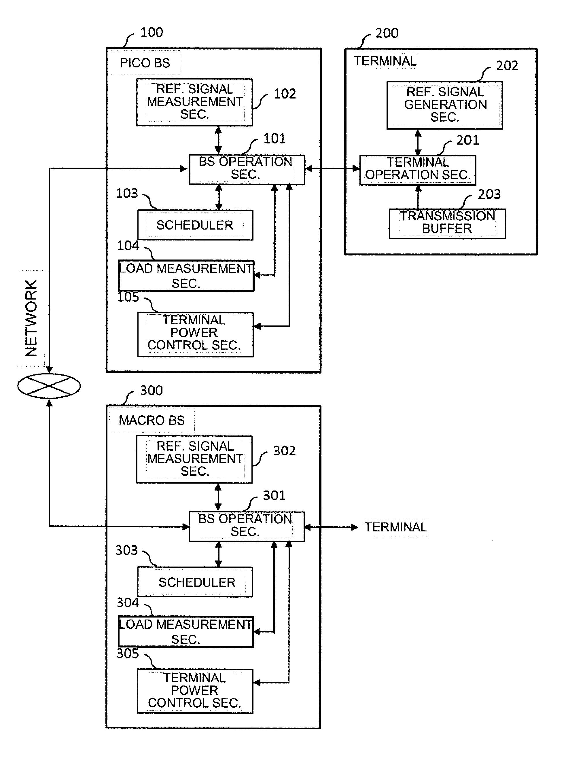
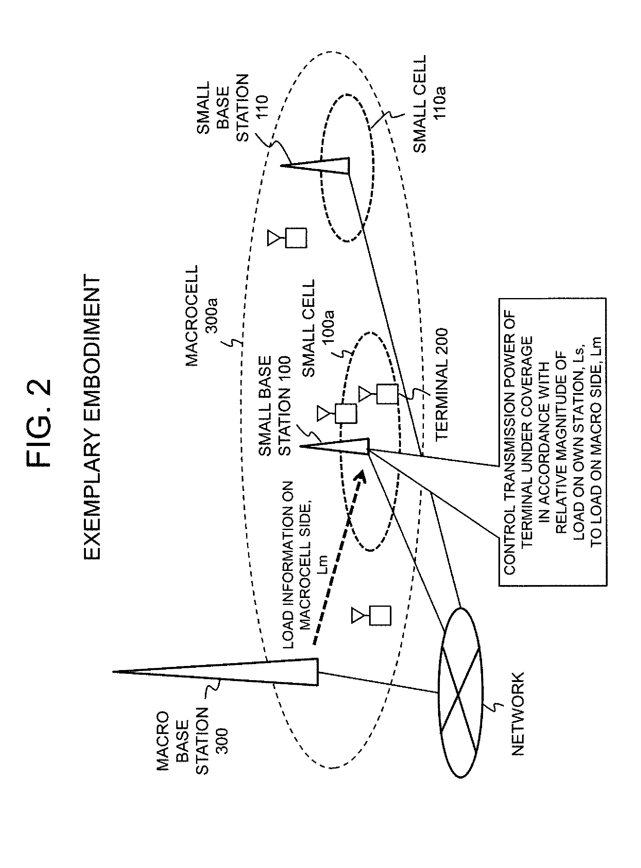
[0045]Referring to FIG. 4, the terminal power control section 105 of the pico base station 100 uses the latest values of the load, PRB usage (PrbUsg_p), on the picocell (own cell) and of the load, PRB usage (PrbUsg_m), on the macrocell (neighbor cell), which is received from the macro base station 300, to calculate the relative load DelPrbUsg in accordance with the following equation (3) (Operation S401):

DelPrbUsg=PrbUsg—p−PrbUsg—m  (3).

[0046]Subsequently, the terminal power control section 105 determines whether or not the transmission power of the terminal 200 is increasing, in accordance with the following expression (4) (Opera...

second example

3.2) Second Example

[0059]According to a second example of the present invention, a PRB usage is used as a load; a load difference is used as a relative load; common target received power Po_No_Pusch (PO—NOMINAL—PUSCH) is used as a transmission power adjustment parameter; and step addition / subtraction is used for adjusting transmission power, which will be described next.

[0060]Referring to FIG. 5, the terminal power control section 105 of the pico base station 100, as in Operation S401 in the first example, uses the latest values of the load, PRB usage (PrbUsg_p), on the picocell (own cell) and of the load, PRB usage (PrbUsg_m), on the macrocell (neighbor cell), which is received from the macro base station 300, to calculate the relative load DelPrbUsg in accordance with the equation (3) (Operation S501).

[0061]Subsequently, the terminal power control section 105 determines whether or not the relative load DelPrbUsg is equal to or more than an increase threshold Th_TpcDelUp for increa...


PUM


Abstract

User throughput fairness between a small cell and a macrocell is improved without affecting load balancing with another small cell. A radio station (100) having a radio area (100a) thereof, at least a part of which is adjacent to a radio area (300a) which is larger than the radio area (100a) of the radio station (100) and is managed by another radio station (300), acquires a load on the own station and a load on the another radio station and controls the transmission power of a radio terminal (200) connected to the radio area of the own cell, based on the relative magnitude of the load on the own cell to the load on the another radio station.

Description

TECHNICAL FIELD[0001]The present invention relates to a radio communication system in which cells of different sizes coexist and, more particularly, to a radio station that controls uplink transmission power from a radio terminal and a method for controlling uplink transmission power.BACKGROUND ART[0002]Radio communication systems such as LTE (Long Term Evolution) and LTE-A (LTE-Advanced) standardized in 3GPP (3rd Generation Partnership Project) are based on the premise that a plurality of radio base stations (hereinafter, referred to as base stations) are deployed, and each base station performs communication with radio terminals (hereinafter, referred to as terminals) in the communication area of the own station. This communication area is referred to as a cell, and a cell can also be divided into a plurality of areas by allowing antennas to have directivity. These divided areas are referred to as sector cells, and it is assumed hereinafter that simply stating “cell” refers to “se...

Claims


Application Information

Patent Timeline
IPC IPC(8): H04W52/34H04W52/26H04W52/36
CPCH04W52/343H04W52/267H04W52/362H04W16/32H04W52/18
Inventor NOBUKIYO, TAKAHIRO
Owner NEC CORP
Why Eureka
Try Eureka