Sensor system and method

Active Publication Date: 2010-11-18
THE UNIV OF SUSSEX
View PDF13 Cites 29 Cited by
  • Summary
  • Abstract
  • Description
  • Claims
  • Application Information

AI Technical Summary

Benefits of technology

[0016]According to another aspect of the invention, there is provided a method of sensing and measuring electrical signals, comprising: detecting the electrical signals; applying the detected signals to an input of a sensor for generating a measurement signal as output; providing a feedback path from an output of the sensor to the input; situating a narrow band filter in the feedback path; controlling the frequency response of the filter whereby to tune the frequency response to a respective one of signals that are wanted signals and signals that represent interference signals; and arranging the sensor and the filter so as to alter the relative amplitudes of the wanted signals and the interference signals in order to increase the relative amplitude of the wanted signals and reduce the relative amplitude of

Problems solved by technology

Various problems associated with the use of extremely sensitive sensors are well known.
One principal problem encountered is that of dynamic range.
This introduces a conflict with the need for high gain in order to amplify small signals and lift them above the noise floor of subsequent stages, such as in analogue to digital (A/D) converters, since such gain cannot be so large that it leads to saturation from large interference signals.
This, however, produces a system which is sensitive to field gradients instead of fields, thus rendering it unsuitable for applications where the source is remote from the sensor.
A problem with the latter approach, however, is that digitising the signal may produce a large dynamic range between the wanted signal and the interference signal.
This A/D converter is seven times more expe

Method used


Image

  • Sensor system and method
  • Sensor system and method
  • Sensor system and method

Examples


Embodiment Construction

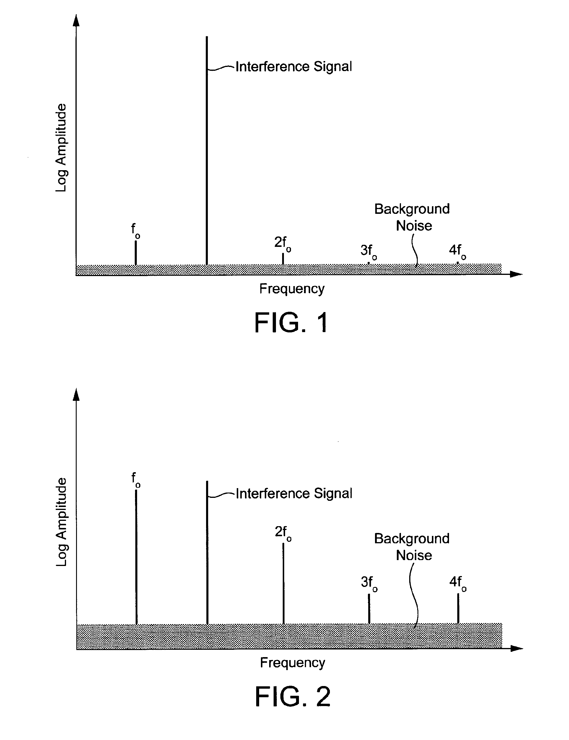
[0037]The invention will now be described with reference to the drawings. Reference is made firstly to FIGS. 1 and 2 for an explanation of the principles of the invention. These Figures are comparative signal diagrams showing frequency against a logarithmic value for amplitude for the various signals encountered by a sensor in practice, including wanted or detection signals and unwanted or interference signals.

[0038]FIG. 1 shows a typical situation where a large interference signal is present amongst the signals received by a conventional sensor. In order to prevent saturation or clipping of the sensor, which would result in dead sensing regions and loss of the wanted signals (fo, 2fo, 3fo and 4fo), the gain of the sensor has hitherto been restricted to a value which keeps the interference signal within the dynamic range of the system, and this introduces the problems referred to above.

[0039]By comparison, in the example of FIG. 2, the frequency response of the sensor has been tailo...


PUM


Abstract

The present invention provides a sensor system and a corresponding sensing method employing the sensor system. The sensor system comprises a sensor (12) having an input (20) and an output (22), a feedback path (16) from the output to the input, and a filter (14; 92) in the feedback path. The filter comprises a narrow band filter, which is tuned or tunable to a respective one of signals that are wanted signals and signals that represent interference signals. The sensor and the filter are arranged so as to alter the relative amplitudes of the wanted signals and the interference signals in order to increase the relative amplitude of the wanted signals and reduce the relative amplitude of the interference signals.

Description

FIELD OF THE INVENTION[0001]The present invention concerns a sensor system for use for the sensitive measurement and detection of signals in a wide variety of applications, and a corresponding sensing method.BACKGROUND OF THE INVENTION[0002]Various problems associated with the use of extremely sensitive sensors are well known. One principal problem encountered is that of dynamic range. A very high sensitivity detector will, of necessity, be required both to accommodate extremely small detected signals and at the same time avoid saturation in the presence of large amplitude interference signals. This introduces a conflict with the need for high gain in order to amplify small signals and lift them above the noise floor of subsequent stages, such as in analogue to digital (A / D) converters, since such gain cannot be so large that it leads to saturation from large interference signals.[0003]The principal interference signals are usually caused by mains related frequencies. These are norm...

Claims


Application Information

Patent Timeline
IPC IPC(8): G01R23/14H03H11/12
CPCH03H11/1291H03H11/1217
Inventor PRANCE, ROBERTPRANCE, HELENHARLAND, CHRISTOPHER
Owner THE UNIV OF SUSSEX
Why Eureka
Try Eureka