Subsurface intrusion detection system

a detection system and subsurface technology, applied in the field of security systems, can solve the problems of high thwarting surveillance techniques that involve observing someone or something crossing the boundary, etc., and achieve the effect of reducing the false alarm rate of existing systems, accurate indication of subsurface activity, and improving the false alarm rate of subsurface activity detection systems

Active Publication Date: 2011-07-14
RAYTHEON BBN TECH CORP +1
View PDF28 Cites 28 Cited by
  • Summary
  • Abstract
  • Description
  • Claims
  • Application Information

AI Technical Summary

Benefits of technology

[0006]The inventors have recognized and appreciated that the false alarm rate of a subsurface activity detection system can be improved through the use of groups of vibration sensors that are deployed with each group having at least a shallower and a deeper sensor. Signal processing to compare relative values for features of the vibrations at related times, detected at each of these sensors provides an accurate indication of subsurface activity. The features compared may include one or more of amplitude, duration and frequency content of the vibrations or other timing metrics or other frequency-domain metrics, In some embodiments, for example, the features compared are amplitude, duration and frequency content. The processing distinguishes between surface activity and subsurface activity, thereby reducing the false alarm rate of the system.

Problems solved by technology

However, surveillance techniques that involve observing someone or something crossing the boundary can be thwarted by tunneling below the surface of the boundary.
However, existing systems have a high false alarm rate from acoustic, RF and surface events.

Method used


Image

  • Subsurface intrusion detection system
  • Subsurface intrusion detection system
  • Subsurface intrusion detection system

Examples


Embodiment Construction

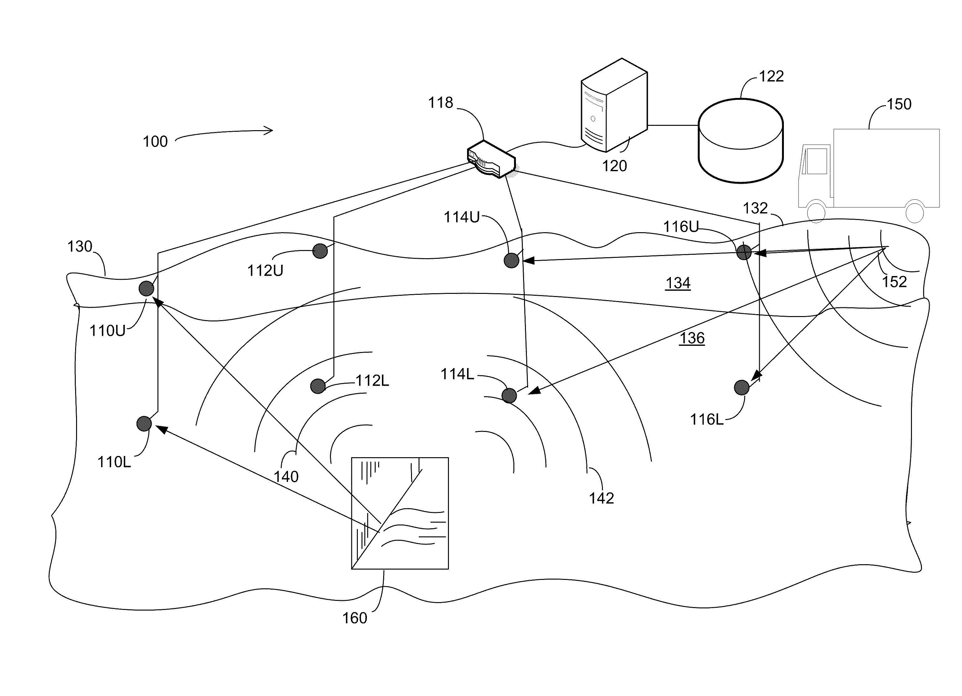
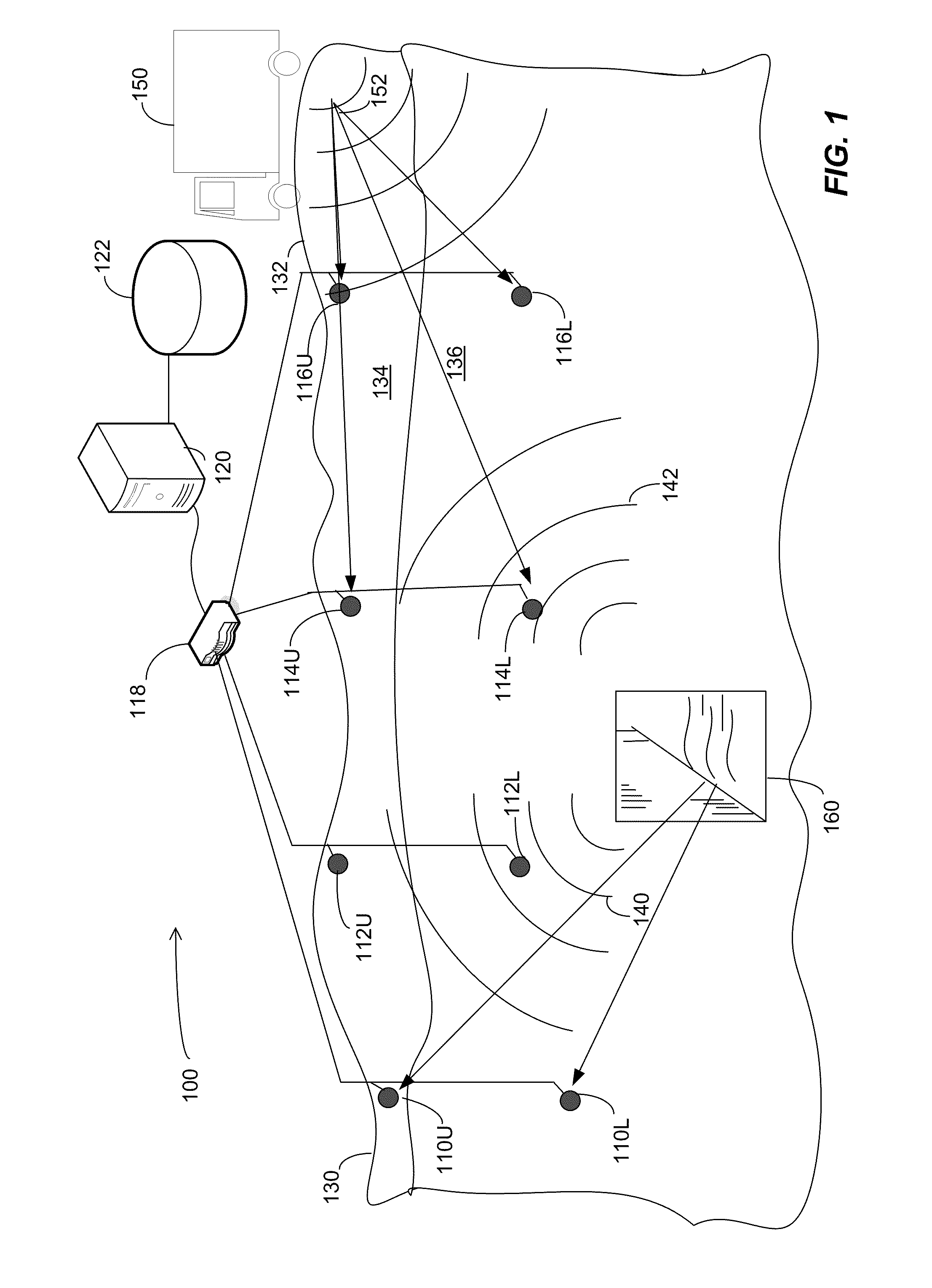
[0018]FIG. 1 illustrates a subsurface intrusion detection system 100 that may accurately detect subsurface activity with a low false alarm rate according to some embodiments of the invention. System 100 may be deployed along any suitable boundary and may be used to detect subsurface activity indicative of digging, unauthorized use of tunnels that pass under the boundary or other surreptitious subsurface activities. System 100 may be employed along any suitable boundary, including the border of a country, a perimeter of a secured facility, such as a prison, or any other location where subsurface activity is to be detected.

[0019]FIG. 1 illustrates a cross section through the earth 130 along the boundary. In this view, multiple vibration sensors, 110U, 110L, 112U, 112L, 114U, 114L, 116U and 116L are visible. Though FIG. 1 shows the sensors along the boundary, it is not a requirement that the sensors be deployed on the boundary. In some embodiments, the sensors may be positioned adjacen...


PUM


Abstract

A system to detect subsurface activity. The system employs vibration sensor pairs, with each sensor pair having a shallow sensor and a deep sensor. Outputs of the sensors of a pair are processed together and events are detected based on the relative values detected by the sensors of the pair. When signal energy departs from a detected background level, the relative amplitude and frequency content of vibrations measured at the shallow and deep sensors may be compared. The comparison may be performed, at least in part, using a classifier that discriminates between subsurface activity and surface to activity. The outputs of sensor pairs may be aggregated to make a determination of whether subsurface activity exists and / or its location. Aggregation may involve comparing the outputs of the same sensor pair at multiple time intervals or may involve comparing the outputs of arrayed sensor pairs.

Description

RELATED APPLICATION[0001]This application is a non-provisional of U.S. Application No. 61 / 151,084, filed Feb. 9, 2009 incorporated herein by reference.BACKGROUND[0002]This invention relates to security systems and more specifically to systems that can detect tunneling or other subsurface activity.[0003]In many instances, it is desirable to secure a boundary. One aspect of securing a boundary is surveillance, which entails identifying when people or objects cross the boundary so that unauthorized movement across the boundary can be prevented. The boundary could be a national border, in which case surveillance may be used to prevent smuggling or illegal immigration. As another example, the boundary could be the perimeter of a secured facility, in which case surveillance may be used to prevent thieves or terrorists from gaining access to the facility. Though, boundary surveillance may also be used to prevent people from leaving a facility, such as a prison.[0004]Various approaches are ...

Claims


Application Information

Patent Timeline
Patent Type & Authority Applications(United States)
IPC IPC(8): G08B13/00
CPCG08B13/1663G01V1/001
Inventor KRUMHANSL, PETER ALLENCONEY, WILLIAMMULLEN, RICHARDMCKENNA, JASON R.GOLDSMITH, MICHAEL
Owner RAYTHEON BBN TECH CORP
Why Eureka
Try Eureka