On-Vehicle Navigation Apparatus And Subject Vehicle Position Correction Method

a technology for vehicle navigation and subject vehicle, applied in navigation instruments, traffic control systems, instruments, etc., can solve the problems of not always being able to accurately determine, redundant execution of auto-reroute is distracting and confusing, and auto-reroute is not executed, etc., to achieve accurate indication on the road

Active Publication Date: 2008-03-27
CLARION CO LTD
View PDF1 Cites 54 Cited by
  • Summary
  • Abstract
  • Description
  • Claims
  • Application Information

AI Technical Summary

Benefits of technology

[0012]According to the present invention, the subject vehicle position and the subject vehicle advancing direction are detected and a specific road to be designated as a map matching candidate is determined based upon the subject vehicle position and the subject vehicle advancing direction having been detected. Then, based upon the results of road marker line detection executed by using a captured image of a road ahead of or behind the subject vehicle, a decision is made as to whether or not the subject vehicle is currently traveling on the map matching candidate road having been determined. Based upon the results of the decision, map matching processing is executed in coordination with the road on which the subject vehicle has been judged to be traveling and the corrected subject vehicle position is thus indicated on the roadmap. As a result, the subject vehicle position can be accurately indicated on the road even when there is a plurality of map matching candidate roads. The auto-reroute can then be executed based upon the subject vehicle position indicated on the map display.

Problems solved by technology

However, over an area such as an area around a branching point, where a plurality of roads are present in close proximity to one another, it may not always be possible to accurately determine to which road the subject vehicle position detection results should be corrected in conjunction with this map matching technology.
The user will find this redundant execution of auto-reroute distracting and confusing.
As a result, even if the current vehicle position is briefly indicated to be off the recommended route due to the position jump phenomenon, the auto-reroute is not executed.

Method used


Image

  • On-Vehicle Navigation Apparatus And Subject Vehicle Position Correction Method
  • On-Vehicle Navigation Apparatus And Subject Vehicle Position Correction Method
  • On-Vehicle Navigation Apparatus And Subject Vehicle Position Correction Method

Examples


first embodiment

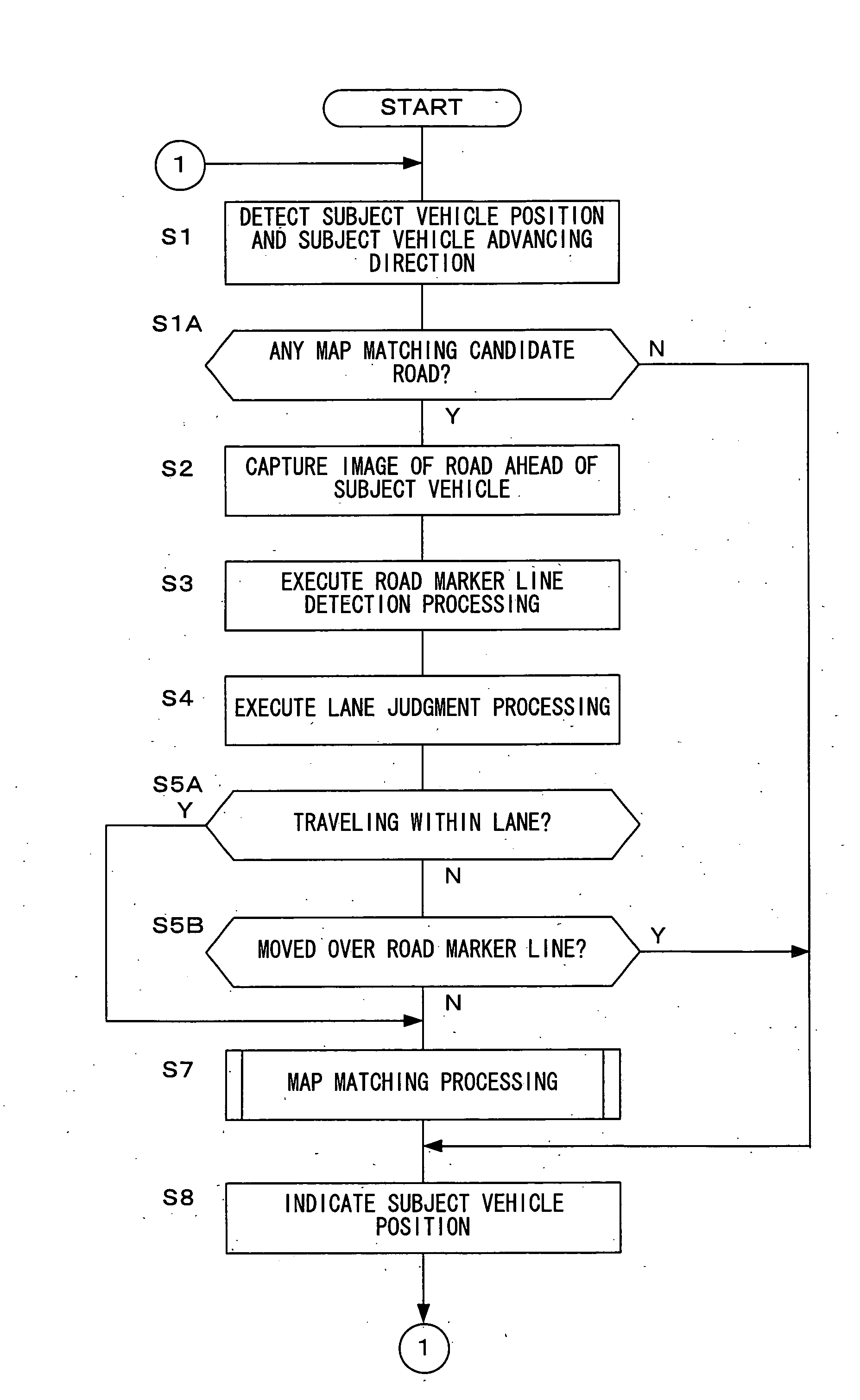
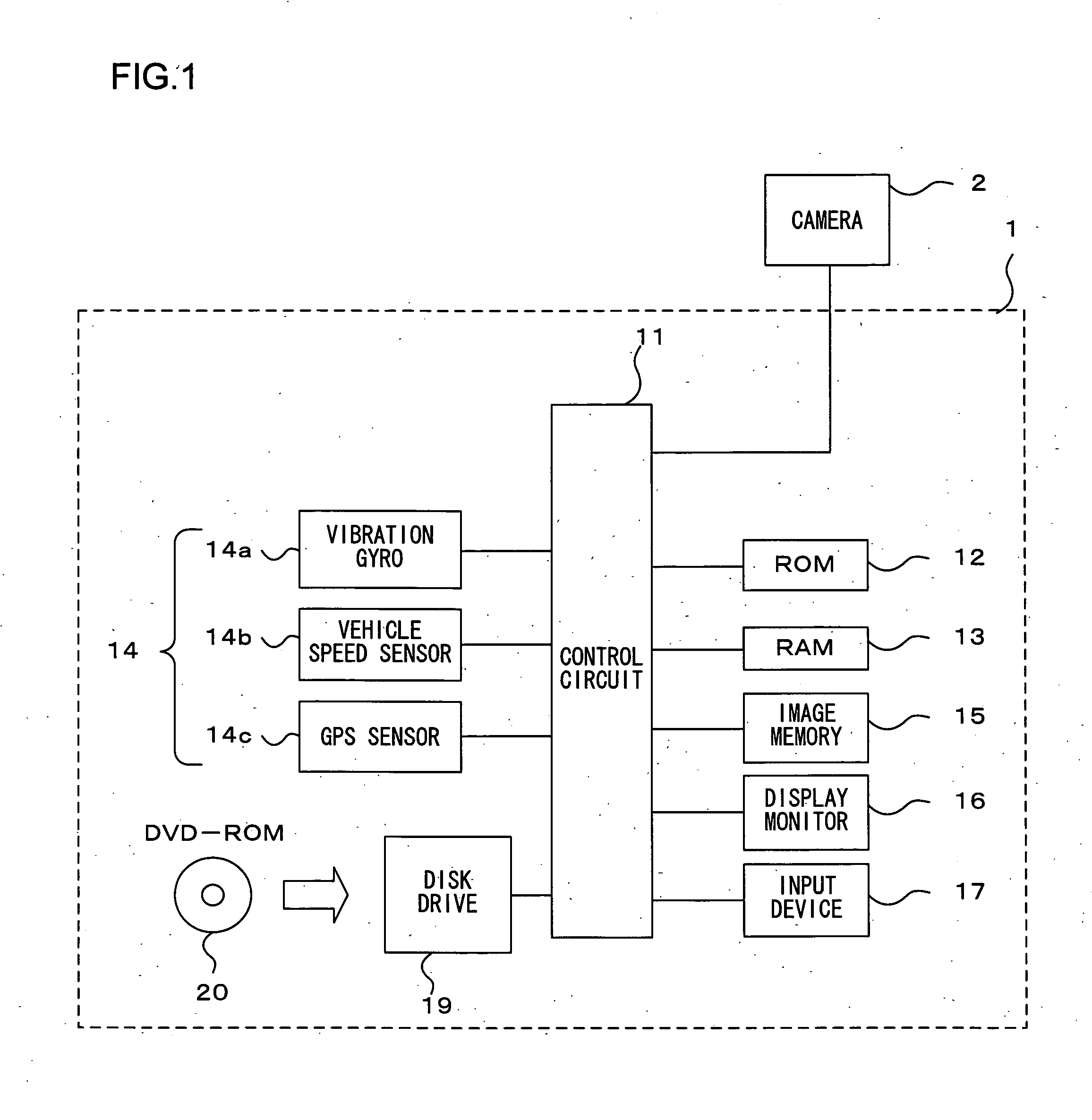
[0020]FIG. 1 shows the structure of the navigation system achieved in an embodiment of the present invention. A navigation system 1 in FIG. 1 accurately indicates the subject vehicle position on a road with improved map matching accuracy by using captured images of the road ahead of the subject vehicle. It is to be noted that the navigation system 1, installed for use in a vehicle, is capable of guiding the subject vehicle to a destination having been set by displaying a roadmap. The navigation system 1 includes a control circuit 11, a ROM 12, a RAM 13, a current position detection device 14, an image memory 15, a display monitor 16, an input device 17 and a disk drive 19. A camera 2 is connected to the control circuit 1, and a DVD-ROM 20 having recorded therein map data is loaded into the disk drive 19.

[0021]The control circuit 11, constituted with a microprocessor and its peripheral circuits, uses the RAM 13 as its work area when executing a control program stored in the ROM 12 to...

second embodiment

[0052]The second embodiment of the present invention is now explained. The navigation system achieved in this embodiment prevents a phenomenon whereby the subject vehicle position is erroneously indicated on a road through map matching when the subject vehicle having entered a parking area or the like on the roadside is not actually traveling on the road. It is to be noted that since the navigation system achieved in the embodiment adopts a structure identical to that shown in FIG. 1 in reference to which the first embodiment has been explained its explanation is omitted.

[0053]Let us now assume that the subject vehicle 100, having been traveling on a road 300, has turned left and entered a parking area 50 on the side of the road 300 as shown in FIG. 5. The road 300 intersects a road 400 beyond the parking area 50. Under such circumstances, if the distance between the point at which the subject vehicle 100 has turned left and the road 400 is within a predetermined distance range set ...


PUM


Abstract

An on-vehicle navigation apparatus comprises a subject vehicle position detection unit that detects a position of a subject vehicle and a direction along which the subject vehicle is advancing, a road marker line detection unit that detects a road marker line in an image of a road captured with a camera, a map matching candidate identifying unit that identifies a road to be designated as a map matching candidate, a decision-making unit that makes a decision as to whether or not the subject vehicle is traveling on the road identified by the map matching candidate identifying unit, a map matching unit that correct the detected subject vehicle position so as to set the subject vehicle position onto the road on which the subject vehicle is determined to be traveling, and a subject vehicle position indicating unit that indicates the subject vehicle position having been corrected.

Description

TECHNICAL FIELD[0001]The present invention relates to an on-vehicle navigation apparatus that indicates the subject vehicle position on a roadmap by adopting a map matching technology.BACKGROUND ART[0002]A known map matching technology is adopted in an on-vehicle navigation system when indicating the subject vehicle position on a roadmap so as to ensure that the subject vehicle indicated on display never erroneously assumes an off road position by correcting the subject vehicle position detection results provided by a GPS, a gyro and the like in correspondence to the road layout. However, over an area such as an area around a branching point, where a plurality of roads are present in close proximity to one another, it may not always be possible to accurately determine to which road the subject vehicle position detection results should be corrected in conjunction with this map matching technology. Under such circumstances, the subject vehicle may be initially indicated on a road on w...

Claims


Application Information

Patent Timeline
Patent Type & Authority Applications(United States)
IPC IPC(8): G01C21/34G01C21/00G09B29/00G01C21/30G08G1/0969G09B29/10
CPCG01C21/30G08G1/0969G06K9/00798G09B29/106G08G1/167G06V20/588
Inventor SUMIZAWA, AKIO
Owner CLARION CO LTD
Why Eureka
Try Eureka