Supercharge Your Innovation With Domain-Expert AI Agents!

Implantable medical device comprising an optical unit

a medical device and optical unit technology, applied in the field of implantable medical devices, can solve the problems of imd's longevity, imd's failure, limitation of their autonomy, etc., and achieve the effect of prolonging the autonomy of the imd

Active Publication Date: 2019-06-06
SYNERGIA MEDICAL
View PDF1 Cites 5 Cited by
  • Summary
  • Abstract
  • Description
  • Claims
  • Application Information

AI Technical Summary

Benefits of technology

The present invention is about an implantable medical device with an optical unit that has better alignment between components, resulting in higher transfer of optical energy and lower power consumption. This allows the device to operate for longer periods of time without needing battery replacement.

Problems solved by technology

Because IMD's must be miniaturized, only small sources of energy are used, limiting their autonomy.
First, the service life of a rechargeable battery depends on the number of charging operations, as the capacity of the battery decreases with each new charging.
Another issue with IMD's is their longevity.
One of the major causes of failures of IMD's is infiltration of alien pollutants—in particular moisture—through degraded joints.
A major issue are feedthroughs, commonly used for conducting electrical current from the outside of an IMD to the inside thereof and reversed.
Several feedthroughs are generally required and forming joints which are tight enough over a long period of exposure to the aggressive environment of a human or animal body is a challenge.
Without surprise, feedthroughs constitute weak points of IMD's which are responsible for many recorded failures.
Considering that the IMD must be miniaturized, thus reducing the size of batteries, which limits the IMD's autonomy and that recharging batteries is a cumbersome operation, it is clear that the coupling efficacy between a fibre optic and the interior of an IMD must be optimized.
Referring to the graphs of FIG. 1, it is clear that it is insufficient for ensuring an efficient transfer of light energy between an outer fibre optic and the interior of an IMD.

Method used


Image

  • Implantable medical device comprising an optical unit
  • Implantable medical device comprising an optical unit
  • Implantable medical device comprising an optical unit

Examples


first embodiment

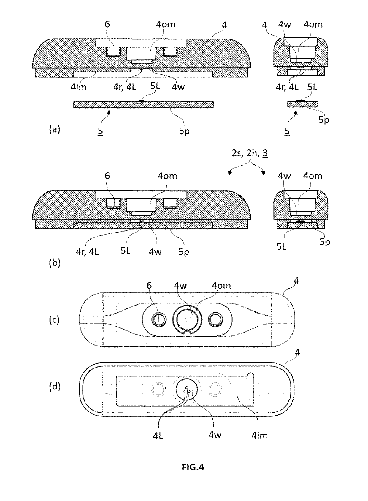
[0063]In a first embodiment, the optical unit (3) can be an integral part of the main housing element (2m) or of the secondary element (2s). For example, FIGS. 3 to 5 illustrate an embodiment wherein the optical unit (3) forms a header (2h) of the housing. Additionally to forming part of the optical unit (3) and to supporting the light unit (5), the monolithic block unit (4) is shaped to form a header fitting an opening (20) provided in the main housing component, and sealed thereto by a secondary joint (7s). In this embodiment, the secondary joint (7s) between the header and the main housing element can advantageously be the sole external joint separating the inner volume from the outer environment. It is preferred that the IMD comprises as single external joint a secondary joint (7s). This is advantageous in that the probability of a leak is reduced. An external joint in the housing is any joint between two elements exposed to both housing inner volume and outer environment. It is...

second embodiment

[0065]In a second embodiment, the optical unit (3) can be sealingly coupled by a hermetic joint (7) to an opening (20) provided in the housing. In one example illustrated in FIG. 6, the optical unit is sealingly coupled to an opening provided in a secondary element (2s) forming a header (2h), by means of a hermetic joint (7). Unlike the monolithic block unit (4), the header (2h) in this embodiment needs not be transparent. The header is sealed to the main housing element by means of a secondary joint (7s).

[0066]In yet another example illustrated in FIG. 7, the optical unit (3) can be sealingly coupled to an opening (20) provided in the main housing element (2m) by means of a hermetic joint (7). Again, the main housing element needs not be transparent. The secondary element (2s) can be a header (2h) or a lid (2L) and can be sealingly coupled to the main housing element by means of a secondary joint (7s).

[0067]In the first embodiment wherein the optical unit (3) is an integral part of...


PUM


Abstract

An implantable medical device (1) is detailed that includes a housing (2) enclosing an electronic circuit and source of power, and an optical unit (3) sealingly coupled to the housing, the optical unit includingmonolithic block unit (4) made of a transparent ceramic material and comprising:a thin window (4w) defined by an inner surface and an outer surface,an outer mating structure (4om) for coupling a fibre optic to the monolithic block, andan inner mating structure (4im) for permanently coupling a light unit, anda light unit (5) rigidly mounted in the inner mating structure (4im) of the monolithic block unit. The light unit includes a light element including one or more of an inner light source (5L), and / or a photodetector (5d), the light element and a fibre optic engaged in the outer mating structure are in alignment with a corresponding reference point (4r) located on the thin window.

Description

TECHNICAL FIELD[0001]The present invention concerns an implantable medical device (IMD) for use in a medical treatment involving the transmission of light through one or more fibre optics, either from or to the implantable medical device. The present invention enhances the longevity of the electronics contained inside the IMD's by reducing the number of joints, preferably down to a single joint, and thus preventing the ingress of moisture and body fluids, as well as protecting the body from pollutants contained within the sealed device. It also increases the efficacy of light transmission by an accurate alignment of the various components of the light transmission assembly to levels never obtained to date in the field of IMD's.BACKGROUND OF THE INVENTION[0002]Implantable medical devices (IMD) have been used for decades for treating a number of disorders, in particular heart and neurological disorders. One type of IMD's consists of neurostimulators, which deliver electrical pulses to...

Claims


Application Information

Patent Timeline
Patent Type & Authority Applications(United States)
IPC IPC(8): A61N5/06A61N1/36G02B6/42
CPCA61N5/0622A61N1/36135G02B6/4246G02B6/4251G02B6/4228G02B6/4204A61N2005/063A61N1/3754A61N5/0601A61N1/36125G02B6/4248G02B6/4292
Inventor DOGUET, PASCALOLBRECHTS, BENOITGODFRAIND, CARMENDE COCK DE RAMEYEN, AURELIE
Owner SYNERGIA MEDICAL
Features
  • R&D
  • Intellectual Property
  • Life Sciences
  • Materials
  • Tech Scout
  • Unparalleled Data Quality
  • Higher Quality Content
  • 60% Fewer Hallucinations
Learn More