
Set Light Fixture and Application of Same

Inactive Publication Date: 2019-06-13
LIU JIANG
View PDF9 Cites 8 Cited by
  • Summary
  • Abstract
  • Description
  • Claims
  • Application Information

AI Technical Summary

Benefits of technology

This patent aims to provide a set light fixture that allows for easy adjustment of its angle and height, as well as easy positioning. It also includes a portable power source for outdoor photographing, and a splicing function to increase the illumination area. Additionally, there is an adapter device that can be used with the adjustment supporting device to enhance the usefulness of the light source device. The adapter device can be detached from the supporting device and used to change the direction of the light source device or attract it to any object. Overall, this invention provides a versatile and convenient light fixture for photographic applications.

Problems solved by technology

However, the traditional LED lamps for photographing or imaging circumstances are generally heavy, and the types of illumination types are relatively limited, and wires are needed to be directly connected to the power source, which results in difficulty in transportation.
In addition, if it is necessary to realize different lighting effects in actual situations, the traditional LED lamps for photographing or imaging circumstances are also difficult to achieve the objects, such as the adjustment of the splicing, replacement, illumination angle range, spot size, and color temperature of the light source according to needs.
However, the actual environments of photographing and imaging circumstances are complex and diverse, it is usually necessary to replace the light source or adjust the angle, position, and color temperature, etc. according to the objective needs of different environments and the subjective needs of different themes, scenes and ideas, etc. by the photographers.
However, the conventional LED lamps for photographing or imaging circumstance are difficult to meet the needs of a variety of complex and varied photographing or imaging environments.

Method used

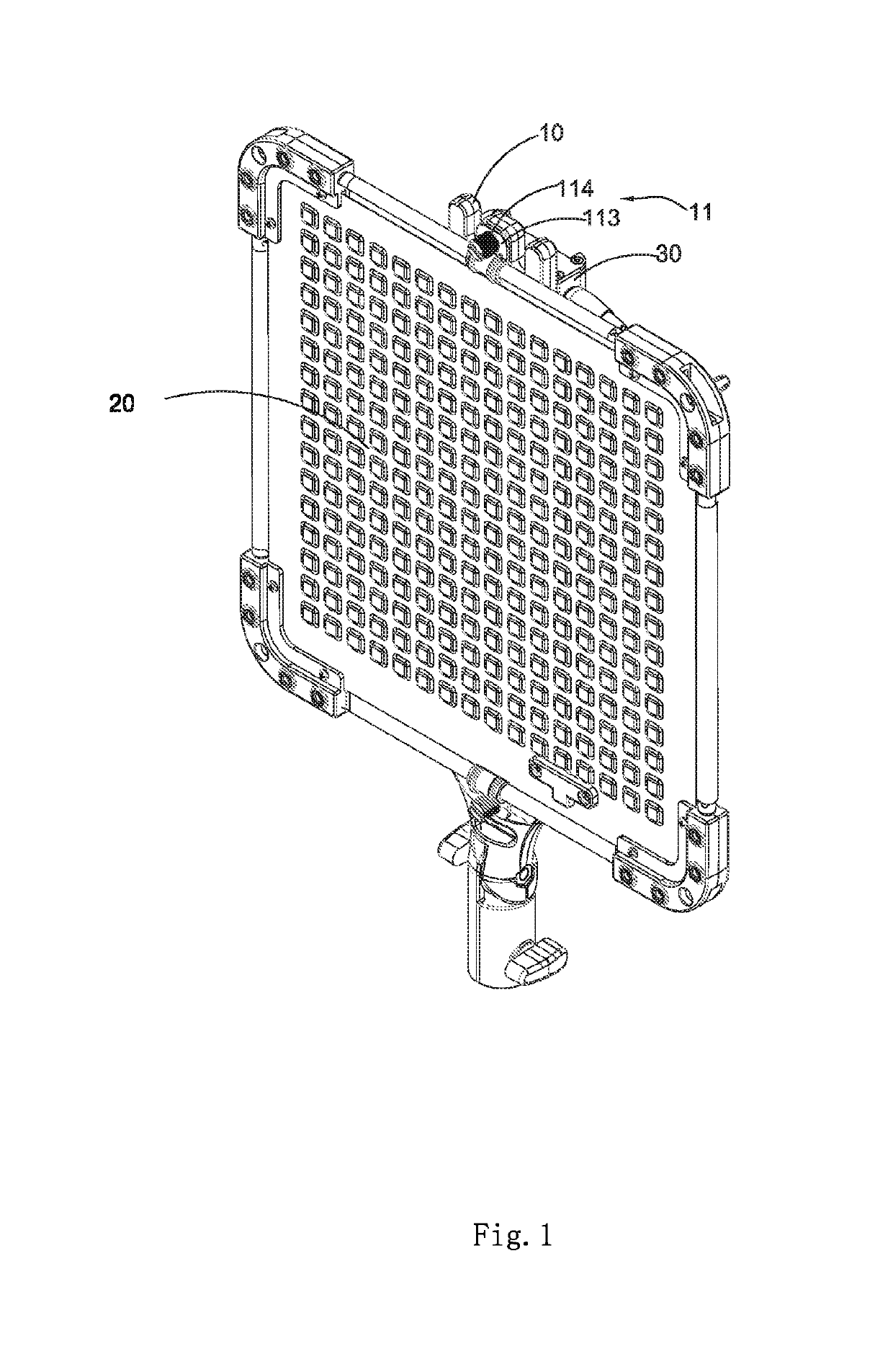
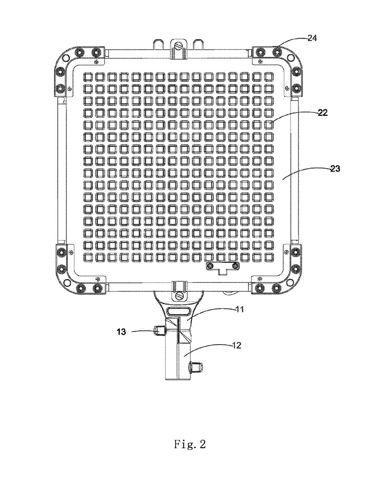
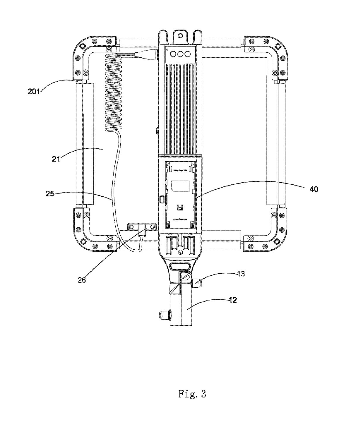

Image

  • Set Light Fixture and Application of Same
  • Set Light Fixture and Application of Same
  • Set Light Fixture and Application of Same

Examples


Embodiment Construction

[0103]The following description is disclosed to enable any person skilled in the art to make and use the present invention. Preferred embodiments are provided in the following description only as examples and modifications will be apparent to those skilled in the art. The general principles defined in the following description would be applied to other embodiments, alternatives, modifications, equivalents, and applications without departing from the spirit and scope of the present invention.

[0104]It should be understood by those skilled in the art that in the disclosure of the present invention, the terms like “longitudinal”, “transverse”, “upper”, “lower”, “front”, “back”, “left”, “right”, “upright”, “horizontal”, “top”, “bottom”, “inside”, and “outside”, etc. which indicates the orientation or positional relationship, is based on the orientation or positional relationship shown in the drawings, which is merely for the convenience of describing the present invention. And the above ...


PUM


Abstract

A set light fixture includes at least one adjustment supporting device, at least one light source device, at least one light control driver, and at least one battery holder. The adjustment supporting device is used to adjust angle and height of the set light fixture. The light source device is removably mounted on the adjustment supporting device. The light control driver is provided on the adjustment supporting device and is electrically connected to the light source device. The battery holder is electrically connected to the light control driver.

Description

CROSS-REFERENCE TO RELATED APPLICATIONS[0001]This is a non-provisional application that claims the benefit of priority under 35 U.S.C. § 371 to international application number PCT / CN2016 / 111611, international filing date Dec. 23 2016, wherein the entire contents of which are expressly incorporated herein by reference.NOTICE OF COPYRIGHT[0002]A portion of the disclosure of this patent document contains material which is subject to copyright protection. The copyright owner has no objection to any reproduction by anyone of the patent disclosure, as it appears in the United States Patent and Trademark Office patent files or records, but otherwise reserves all copyright rights whatsoever.BACKGROUND OF THE PRESENT INVENTIONField of Invention[0003]The present invention relates to an illumination device, and more particularly to a set light fixture for conveniently changing an illumination angle and an illumination height to meet needs of a variety of situations where illumination or speci...

Claims


Application Information

Patent Timeline
IPC IPC(8): F21V21/30F21L4/04G03B15/02F21V21/14F21V29/70
CPCF21V21/30F21L4/04G03B15/02F21V21/145F21V29/70F21Y2115/10F21Y2105/12G03B2215/0567F21S8/00
Inventor LIU, JIANG
Owner LIU JIANG
Learn More