
Distance measurement device and distance measurement method

Active Publication Date: 2019-06-13
HITACHI LTD
View PDF1 Cites 0 Cited by
  • Summary
  • Abstract
  • Description
  • Claims
  • Application Information

AI Technical Summary

Benefits of technology

This invention can accurately generate information about distance. This can be useful in various applications.

Problems solved by technology

However, the configuration of the imaging device may be affected by a blurred shape in defocus, thereby causing a significant error in distance information.

Method used


Image

  • Distance measurement device and distance measurement method
  • Distance measurement device and distance measurement method
  • Distance measurement device and distance measurement method

Examples


first embodiment

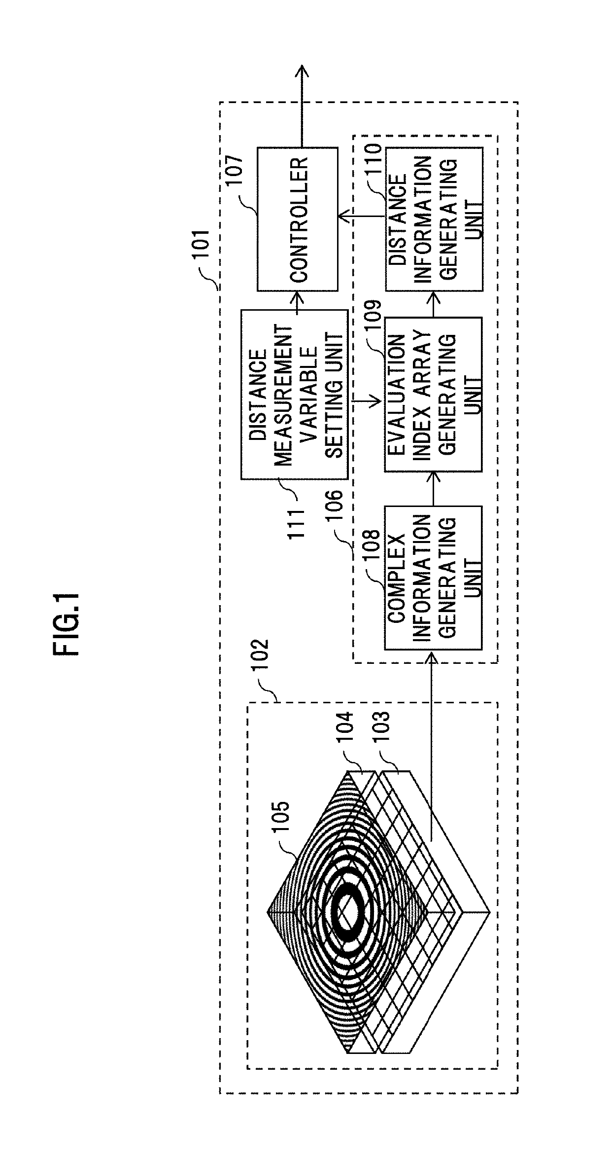
[0057]FIG. 1 shows a configuration example of a distance measurement device 101 as a first embodiment according to the present invention.

[0058]The distance measurement device 101 is adapted to capture an image of an external object without using any lens for imaging, and composed of, as shown in FIG. 1, an imaging unit 102, an image processing unit 106, a controller 107, and a distance measurement variable setting unit 111.

[0059]The image processing unit 106 includes a complex information generating unit 108, an evaluation index array generating unit 109, and a distance information generating unit 110.

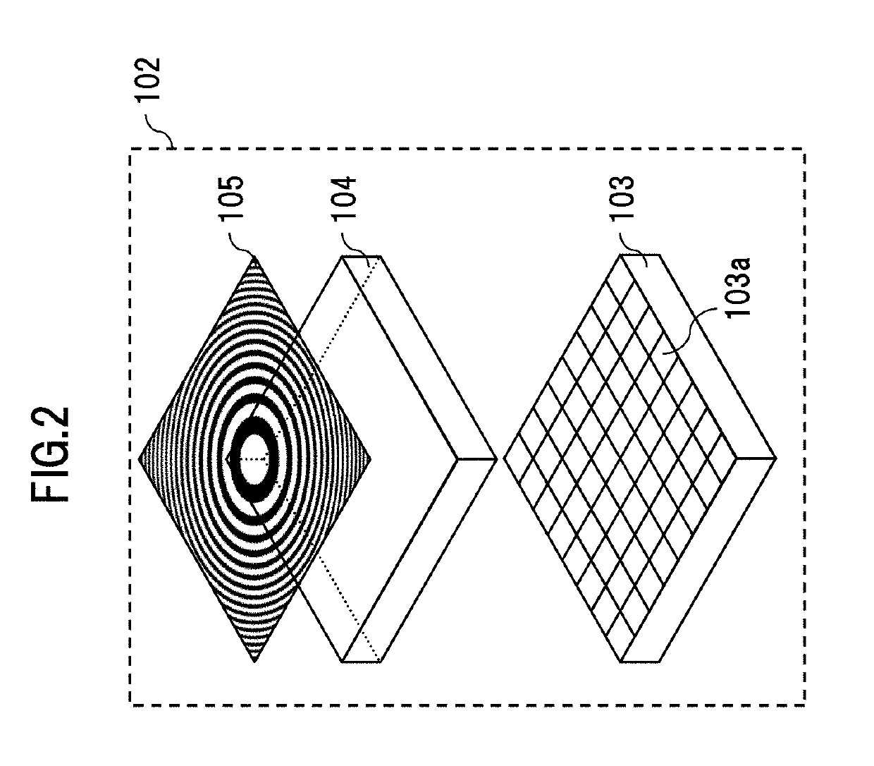
[0060]FIG. 2 shows a configuration example of the imaging unit 102. The imaging unit 102 is composed of an image sensor 103, a pattern substrate 104, and a pattern 105 for shooting.

[0061]One flat surface of the pattern substrate 104 is fixed in close contact with the light-receiving surface of the image sensor 103, and the pattern 105 for shooting is formed on the other flat surface of...

second embodiment

[0124]Next, FIG. 39 shows a configuration example of a distance measurement device 1011 as a second embodiment according to the present invention.

[0125]The distance measurement device 1011 obtained by adding a distance measurement range input unit 3101 to the distance measurement device 101 (FIG. 1), differs in calculating, in a non-search manner, the coefficient β′ for a pattern 1801 for evaluation index array generation such that an evaluation index array meets a predetermined requirement.

[0126]The distance measurement range input unit 3101 of the distance measurement device 1011 accepts a distance measurement range that is input by a user, and supplies the range to the distance measurement variable setting unit 111. The user inputs the distance measurement range, for example, by specifying the nearest distance LN and furthest distance LF of the distance measurement range.

[0127]The distance measurement variable setting unit 111 determines, based on the nearest distance LN and the ...

third embodiment

[0136]Next, a distance measurement device as a third embodiment according to the present invention will be described. The distance measurement device as the third embodiment is configured in a similar fashion as the distance measurement device 101 (FIG. 1), but different in that distance information is generated on the basis of the phase angle of an evaluation index array.

[0137]FIG. 43 shows the result of plotting a phase angle of the result of a cross-correlation operation with complex information 1602 and a pattern 1801 for evaluation index array generation, with respect to a coefficient β′ for the pattern 1801 for evaluation index array generation.

[0138]The phase angle changes in a linear manner with respect to the coefficient β′, and intersects with 0 at a point of β′=β0. For this reason, in the evaluation index array generating unit 109, based on the result of the cross-correlation operation with the complex information 1602 and the patterns 1801 for evaluation index array gene...


PUM


Abstract

A distance measurement device is characterized in that the device includes: an image sensor configured to convert light to electrical signals to generate a sensor image; a modulator configured to modulate the intensity of light projected on the image sensor, based on a pattern for shooting; a complex information generating unit configured to generate, from the sensor image, complex information including a complex number; an evaluation index array generating unit configured to generate an evaluation index array, based on phase information of the complex information; and a distance information generating unit configured to generate distance information, based on the evaluation index array.

Description

[0001]This application claims the priority based on the Japanese Patent Application No. 2017-236633 filed on Dec. 11, 2017. The entire contents of which are incorporated herein by reference for all purpose.BACKGROUNDTechnical Field[0002]The present invention relates to a distance measurement device and a distance measurement method.Related Art[0003]The international publication No. WO2017 / 149687 discloses, as a configuration for achieving a high-function imaging device which performs focusing after shooting (refocusing), auto focus, ranging, and the like, “an imaging device including: an image sensor configured to convert an optical image captured in a plurality of pixels arranged in an array form at an imaging surface, to image signals, and outputs the image signals; a modulator provided on a light-receiving surface of the image sensor and configured to modulate the intensity of light; an image storage unit configured to temporarily store image signals output from the image sensor;...

Claims


Application Information

Patent Timeline
IPC IPC(8): H04N5/232G02F1/1343
CPCH04N5/232122G02F1/134309G02F2201/122H04N23/959H04N23/633H04N23/672
Inventor YAMAGUCHI, KEITANAKAMURA, YUSUKE
Owner HITACHI LTD
Features
  • Generate Ideas
  • Intellectual Property
  • Life Sciences
  • Materials
  • Tech Scout
  • Unparalleled Data Quality
  • Higher Quality Content
  • 60% Fewer Hallucinations
Learn More