
Front Loader and Working Machine

a front loader and working machine technology, applied in mechanical machines/dredgers, soil-shifting machines/dredgers, constructions, etc., can solve problems such as the risk of taking time to store the stand

Active Publication Date: 2019-06-27
KUBOTA CORP
View PDF0 Cites 0 Cited by
  • Summary
  • Abstract
  • Description
  • Claims
  • Application Information

AI Technical Summary

Benefits of technology

[0006]The present invention provides a front loader and a working machine in which a stand can be raised smoothly with a simple structure even if a bending / stretching link has strong bending resistance.
[0037]According to the present configuration, it is easy to raise the stand even if the bending / stretching link has strong bending resistance, making it possible to immediately start a loader operation after coupling the front loader.

Problems solved by technology

To fold the stand to be compact, using a bending / stretching link as the support link has also been considered, but there may be cases where the bending / stretching link is unlikely to bend due to strong bending resistance, and thus there is the risk that it will take time to store the stand.

Method used


Image

  • Front Loader and Working Machine
  • Front Loader and Working Machine
  • Front Loader and Working Machine

Examples


Embodiment Construction

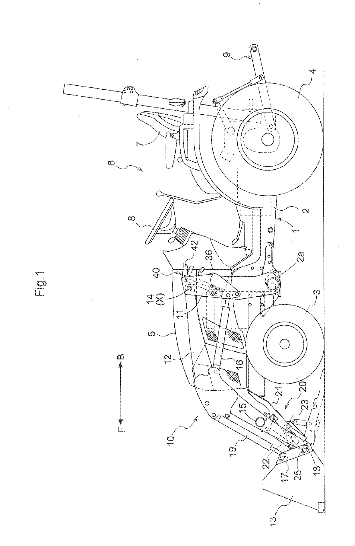
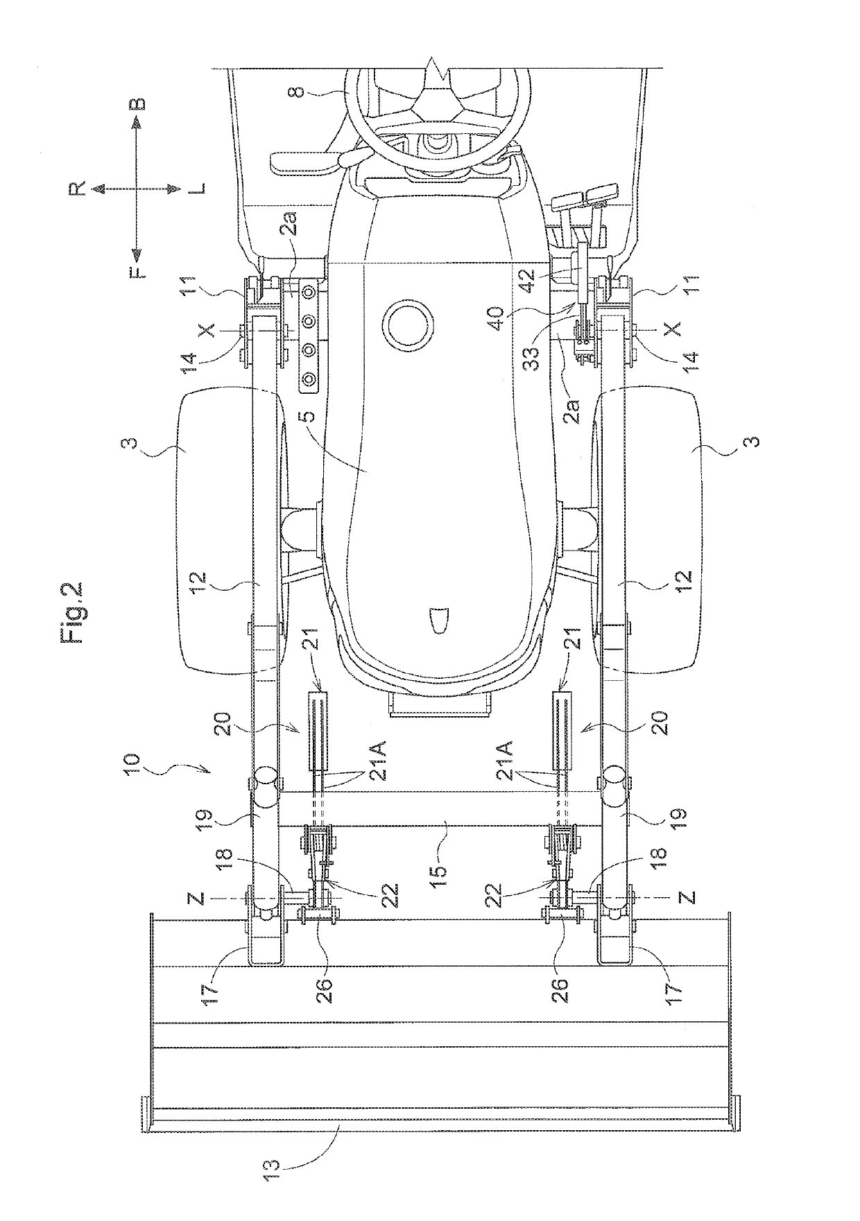
[0055]The following will describe embodiments of the present invention when it is applied to a tractor, which is an example of a working vehicle, with reference to the drawings. FIG. 1 is a left side view showing the tractor in its entirety. FIG. 2 is a plan view showing a front portion of the tractor. In FIGS. 1 and 2, the forward direction of a travel vehicle body 1 is defined as a direction [F], and the backward direction of the travel vehicle body 1 is defined as a direction [B], and in FIG. 2, the leftward direction of the travel vehicle body 1 is defined as a direction [L], and the rightward direction of the travel vehicle body 1 is defined as a direction [R].

Overall Structure of Tractor

[0056]As shown in FIGS. 1 and 2, the tractor includes the travel vehicle body 1 including a vehicle body frame 2 that supports, in its front portion, a pair of left and right front wheels 3 so that they are drivable and steerable, and supports, in its rear portion, a pair of left and right rear...


PUM


Abstract

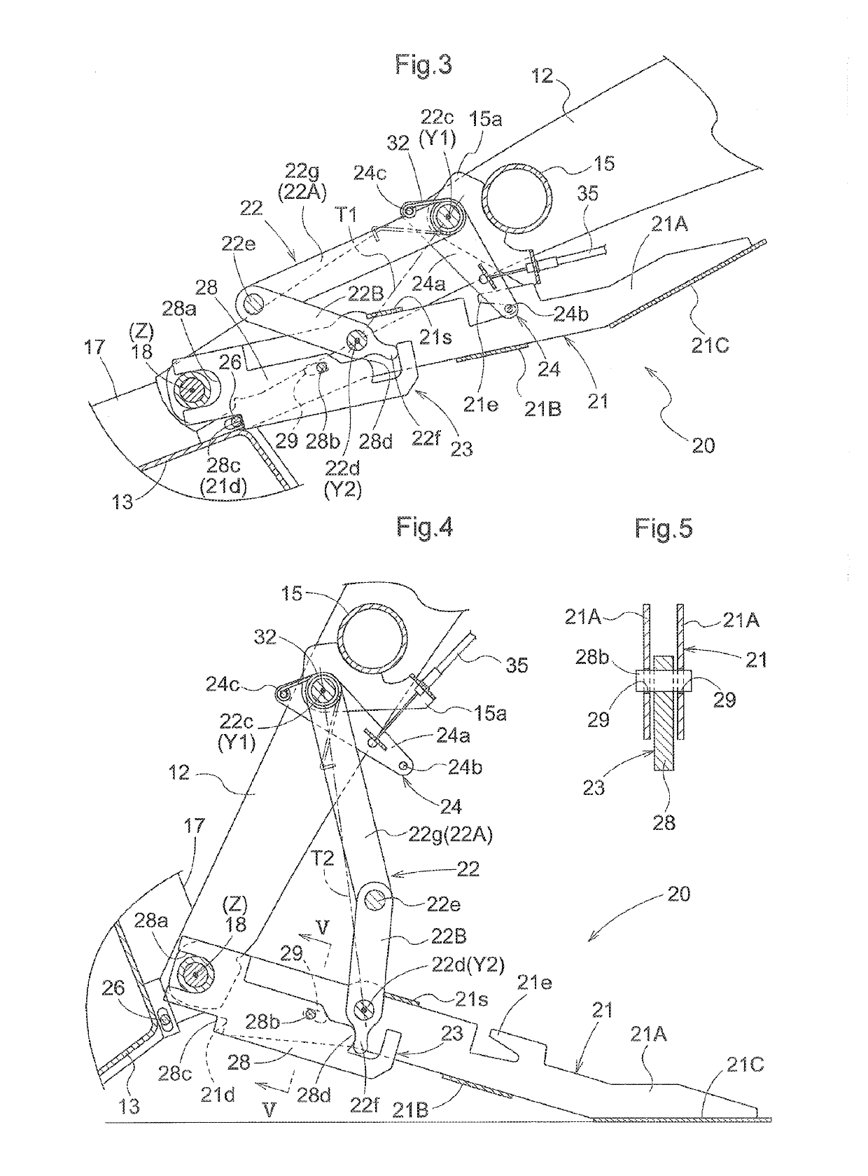
A link operating mechanism is provided spanning a bucket and a stand. The link operating mechanism causes, using a swing force of the bucket, a bending or stretching link to bend so that propping and supporting of the bending or stretching link are released.

Description

CROSS REFERENCE TO RELATED APPLICATION[0001]This application is a continuation of U.S. patent application Ser. No. 15 / 855,096 filed Dec. 27, 2017, which is hereby incorporated by reference in its entirety herein.BACKGROUND OF THE INVENTIONField of the Invention[0002]The present invention is directed to a front loader and a working machine provided with the front loader.Description of Related Art[0003]As front loaders, there are ones including: a boom removably coupled to a vehicle body; a bucket supported at a front end of the boom; a stand that supports the boom, when removed from the vehicle body, in a state in which the bucket is engaged on the ground; and a support link that is provided spanning the boom and the stand, and is configured to prop and support the stand in the grounded state.[0004]For example, U.S. Pat. No. 4,347,031 discloses a front loader of this type. The front loader disclosed in U.S. Pat. No. 4,347,031 includes a stand body serving as the stand, and a slide me...

Claims


Application Information

Patent Timeline
Patent Type & Authority Applications(United States)
IPC IPC(8): E02F3/627E02F3/34E02F3/38
CPCE02F3/34E02F3/6273E02F3/382E02F3/961E02F3/28E02F3/36E02F3/40E02F3/401E02F3/42
Inventor BOYD, ROBERT STEWART
Owner KUBOTA CORP
Learn More