Work Vehicle and Front Grill of Work Vehicle

Active Publication Date: 2020-09-03
KUBOTA LTD
View PDF0 Cites 0 Cited by
  • Summary
  • Abstract
  • Description
  • Claims
  • Application Information

AI Technical Summary

Benefits of technology

The invention relates to a configuration for a brake system for a vehicle. The technical effect of the configuration is that it can resolve any jamming that might occur between the upper link and the wheel support member, or between the lower link and the wheel support member, by deforming the elastic member. This allows the brakes to operate smoothly and ensures that the vehicle travels smoothly. Additionally, the configuration may reduce the amount of reflected light from the front side, which can be achieved by providing an inclined face that intersects incident light from the front.

Problems solved by technology

As the position shift in the front-rear direction increases between the one of the traveling wheels and the other one of the traveling wheels, the tilt angle of the wheel support member relative to the vehicle-body front-rear direction in a plan view increases, and thus, yawing of the vehicle body is likely to occur.
However, the technique described in this structure has the following problem in the case of applying this technique to a work vehicle.
However, if, for example, a non-porous flat plate body is attached to the bottom face side of the recessed areas in portions where ventilation is not needed, the recessed areas are likely to be recognized as being not very deep and being shallow in a front view thereof unless the recessed areas are made considerably deep, and there is concern that this will not give a dignified impression and will have a negative affect on the appearance thereof.

Method used


Image

  • Work Vehicle and Front Grill of Work Vehicle
  • Work Vehicle and Front Grill of Work Vehicle
  • Work Vehicle and Front Grill of Work Vehicle

Examples


first embodiment

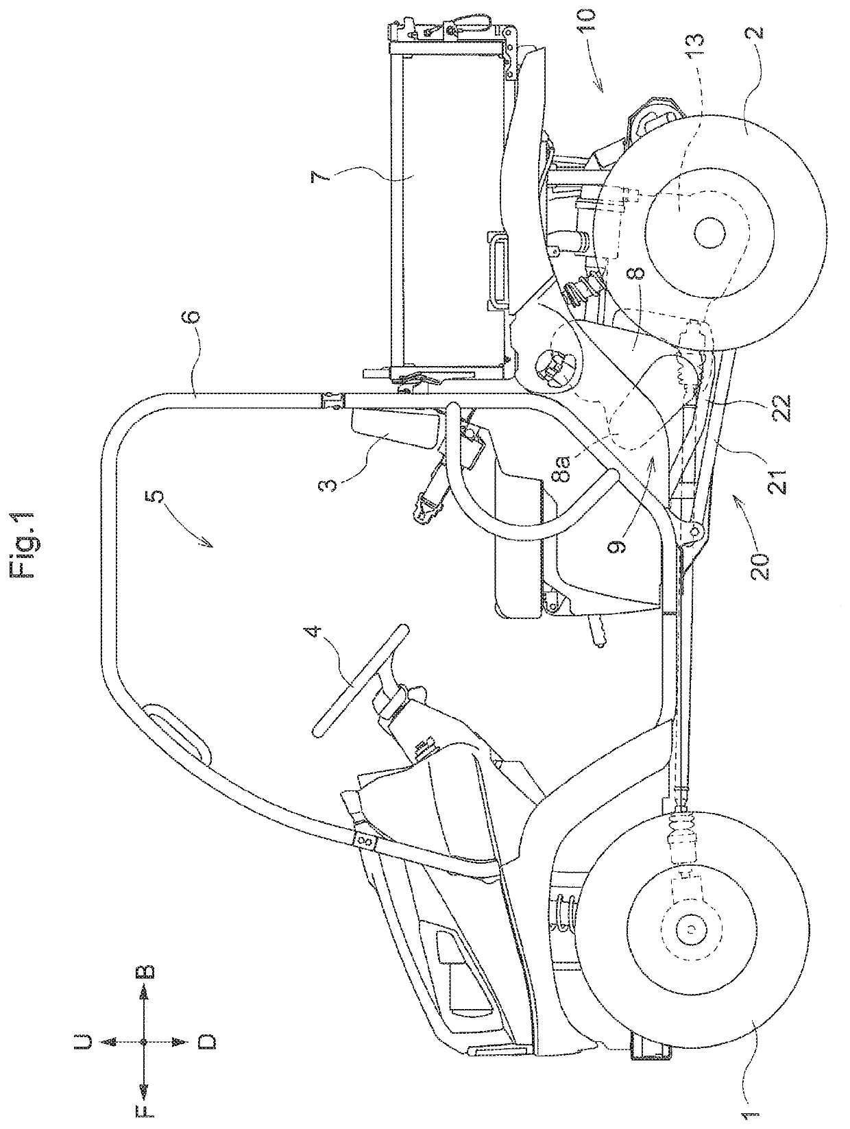
[0176]1 Traveling wheel (rear wheel)

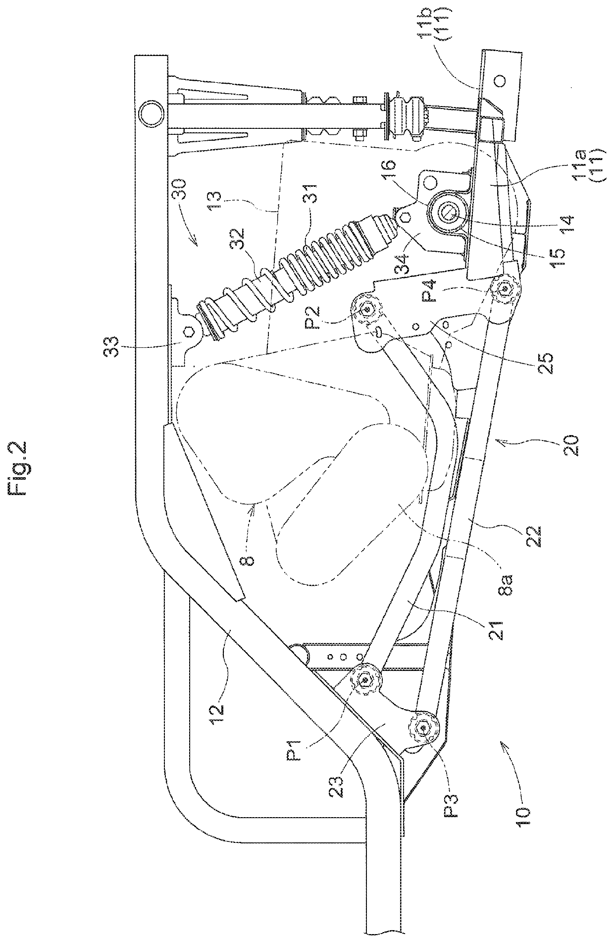
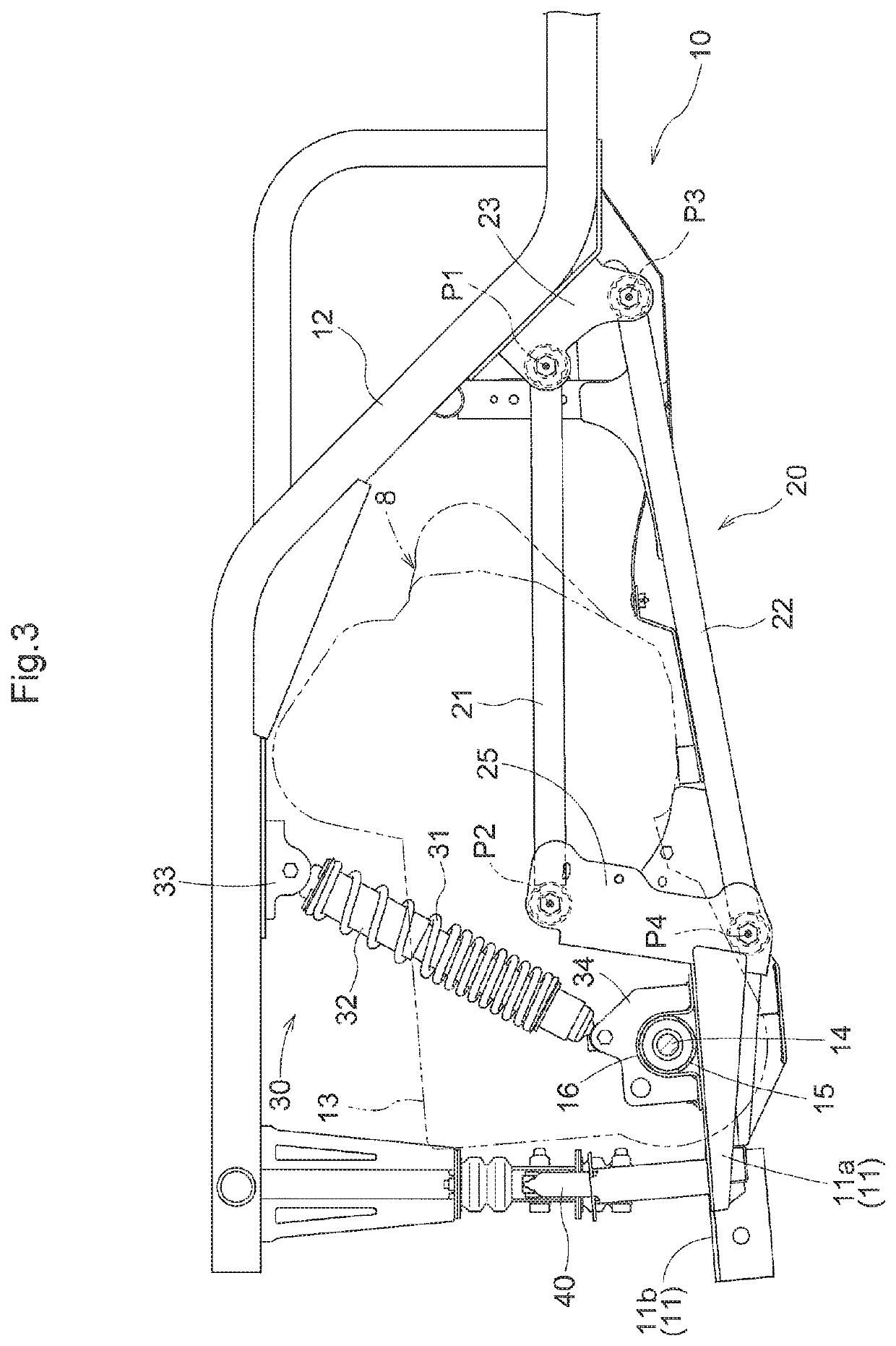
[0177]11 Wheel support member

[0178]20 Link mechanism

[0179]21 Upper link

[0180]22 Lower link

[0181]23 Link support portion

[0182]29 Elastic member

[0183]30 Suspension mechanism

[0184]33 Suspension support portion

[0185]40 Lateral link

[0186]40a End portion

[0187]41 Vehicle body-side support portion

[0188]42 Wheel-side support portion

[0189]42a Vertical plate portion

[0190]42b Joint plate portion

[0191]42c Upper plate portion

[0192]43 Screw shaft member

[0193]51 Cushion material

[0194]P1 Upper pivot axis

[0195]P2 Upper joint axis

[0196]P3 Lower pivot axis

[0197]P4 Lower joint axis

[0198]DL Distance (between lower pivot axis and lower joint axis)

[0199]FD Gap width (gap width between upper pivot axis and lower pivot axis)

[0200]RD Gap width (gap width between upper joint axis and lower joint axis)

[0201]UL Distance (between upper pivot axis and upper joint axis)

second embodiment

[0202]101 Vehicle body frame

[0203]102 Heat-insulating cover

[0204]102a Open hole

[0205]140 Engine

[0206]140A Engine body

[0207]144 Exhaust manifold

[0208]145 Collecting pipe portion

[0209]145a Path

[0210]145d Joint bolt

[0211]147 Exhaust manifold cover

[0212]147a Inclined face

[0213]148 Rivet

third embodiment

[0214]232, 233 Bridge member

[0215]234 Recessed portion

[0216]234a Bottom face portion

[0217]235 Small protruding portion

[0218]235a Inclined face


PUM


Abstract

A work vehicle includes: a wheel support member configured to support a pair of left and right traveling wheels; a link mechanism configured to support the wheel support member such that the wheel support member can be raised and lowered, the link mechanism being provided spanning between a vehicle body and the wheel support member; a suspension mechanism configured to elastically support the wheel support member, the suspension mechanism being provided spanning between a suspension support portion, which is formed on the vehicle body, and the wheel support member; and a lateral link configured to restrict leftward and rightward movement of the wheel support member, the lateral link being joined to a vehicle body-side support portion, which is formed on the vehicle body, and to a wheel-side support portion, which is formed on the wheel support member, wherein the link mechanism has: an upper link with an front end portion supported so as to be able to pivot up and down around an upper pivot axis by a link support portion, which is formed on the vehicle body, and with a rear end portion joined so as to be able to relatively pivot around an upper joint axis by the wheel support member; and a lower link with a front end portion supported so as to be able to pivot up and down around a lower pivot axis by the link support portion, and with a rear end portion joined to the wheel support member so as to be able to relatively pivot around a lower joint axis, a distance between the upper pivot axis and the upper joint axis is set shorter than a distance between the lower pivot axis and the lower joint axis, a gap width between the upper joint axis and the lower joint axis is set larger than a gap width between the upper pivot axis and the lower pivot axis, and when the vehicle body is in an unloaded state, the lower joint axis is located lower than the lower pivot axis.

Description

CROSS-REFERENCE TO RELATED APPLICATIONS[0001]This application claims priority to Japanese Patent Application No. 2019-037413 filed Mar. 2, 2019, and Nos. 2019-060508 and 2019-060509 filed Mar. 27, 2019, the disclosures of which are hereby incorporated by reference in their entirety.BACKGROUND OF THE INVENTION1. Field of the Invention[0002]The present invention relates to a work vehicle.[0003]Also, the present invention relates to a work vehicle in which an exhaust manifold cover that covers the upper side of an exhaust manifold, which is continuous with cylinders in an engine body, is provided adjacent to the engine body.[0004]The present invention relates to a front grill with a structure in which a large number of bridge members, which intersect each other in a front view thereof, are provided, and a large number of recessed portions, which are recessed toward the back side, are formed in portions surrounded by the bridge members.2. Description of the Related Art[Background Art 1]...

Claims


Application Information

Patent Timeline
IPC IPC(8): B60G3/20B60G15/06F01N13/10B60K11/08
CPCF01N13/102B60G2202/12B60G2204/4102B60G2202/20B60G15/062B60G2200/144B60G3/20B60K11/08B60G2202/312F01N2260/20F01N2590/00F01N13/10B60K13/04B60Y2200/20B60K5/04B60K2005/003B60G9/022B60G2200/314B60G2300/13
Inventor AZUMA, MASAHIRONAGATOMI, TATSUYAMORIBE, KENTAKANEKO, TOMONORI
Owner KUBOTA LTD
Why Eureka
Try Eureka