Overhead transport vehicle and transport system

a technology for transporting vehicles and transportation systems, applied in the direction of cleaning processes, cleaning processes, lifting devices, etc., can solve the problems of reducing transport efficiency, prolonging the time, and stutter cranes, so as to facilitate the expansion of the ascending/descending range of the elevation platform, avoid interference of the lower portion, and simple operation

Active Publication Date: 2020-02-13
MURATA MASCH LTD
View PDF8 Cites 1 Cited by
  • Summary
  • Abstract
  • Description
  • Claims
  • Application Information

AI Technical Summary

Benefits of technology

[0010]An overhead transport vehicle according to a preferred embodiment of the present invention is capable of easily expanding an ascending / descending range of the elevation platform by connecting the lower mast to the upper mast. The lift driver is supported by the traveling body even when the lower mast is separated from the upper mast. Therefore, an upper structure and a lower structure are able to be separated by a simple operation such as removal of the lower mast from the upper mast. Since the upper mast, the elevation platform, and the lift driver are supported in a compact form by the traveling body, the upper mast, the elevation platform, and the lift driver are able to be easily moved to another location along with the traveling body after the upper mast has been separated from the lower mast. In other words, the traveling body is able to travel in the state of consolidating, on the upper mast (in the upper structure), all of the elements required to raise and lower the elevation platform. Also, the elevation platform is able to be raised or lowered along the upper mast after the lower mast has been separated from the upper mast.
[0011]In the example where the lower end position of the upper mast is set lower than the lower end of the elevation platform positioned at an upper limit of a movable range thereof, the lower portion of the elevation platform does not project to the lower side of the upper mast when the elevation platform is positioned at the upper limit of the movable range thereof. Therefore, when the traveling body is moved after having separated the upper mast from the lower mast, it is possible to avoid interference of the lower portion of the elevation platform with other portions. In the example where the lower mast connected to the upper mast and a member attached to the lower mast are not in contact with the floor surface side of the facility when the traveling body is traveling, the lower structure including the lower mast is not in contact with the floor surface, and therefore, the traveling load of the overhead transport vehicle is able to be reduced.
[0012]In the example where the elevation platform includes the plurality of mast guides for the elevation platform to ascend or descend along the upper mast or the lower mast, the elevation platform is able to be smoothly raised or lowered along the upper mast or the lower mast. In the example where the overhead transport vehicle further includes the transferor that is provided on the elevation platform and that transfers the article, the transfer device is able to easily transfer the article to a transfer destination.
[0013]Since a transport system according to a preferred embodiment of the present invention uses the overhead transport vehicle mentioned above, the overhead transport vehicle can be used in a mode selected from two modes, namely the state of having the upper mast only and the state of having the lower mast connected, and as a result, transport mode versatility of the overhead transport vehicle is improved. In the example where the transport system further includes the support that supports the lower mast when disconnected from the upper mast, the support is able to prevent the lower mast having been separated from the upper mast, from falling down.
[0014]In the example where the transport system further includes the lifter that is able to be connected to the track and that causes the overhead transport vehicle having been disconnected from the lower mast to move in the vertical direction, the overhead transport vehicle that has separated the lower mast therefrom is able to easily be raised or lowered by the lifter between the track and a maintenance position on the lower side thereof, or between the track and another track on the lower side thereof. In the example where the transport system further includes the second lower mast that is connected to the lower end of the upper mast via a connector in the freely detachable manner, that includes a lower guide that extends to the upper guide, and that has a length that is different from that of the lower mast, the ascending / descending range of the elevation platform is able to be easily changed by connecting the upper mast to the second lower mast.

Problems solved by technology

However, the stacker crane of Japanese Patent No. 5545498 has a problem.
The stacker crane, when separating the masts, requires troublesome work such as an operation of removing the elevating belts from the masts, which not only is time consuming but also prolongs the time of interruption in article transportation, resulting in reduced transport efficiency.
Further, the separated upper structure does not have a function of raising or lowering the elevation platform and is incapable of transporting articles.

Method used


Image

  • Overhead transport vehicle and transport system
  • Overhead transport vehicle and transport system
  • Overhead transport vehicle and transport system

Examples


first preferred embodiment

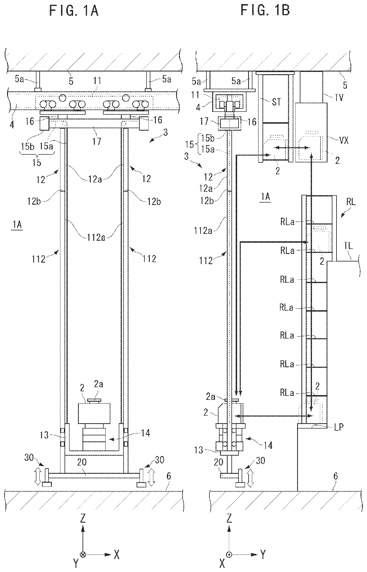
[0029]FIGS. 1A and 1B are diagrams showing examples of a transport system to which an overhead transport vehicle related to the present preferred embodiment is applied. A transport system 1A of the present preferred embodiment preferably is installed in a semiconductor device manufacturing factory, for example, and is applied to a system that transports articles 2 such as FOUPs (Front Opening Unified Pods) accommodating semiconductor wafers used for manufacturing semiconductor devices, and reticle pods accommodating processing members such as reticles, for example. Here, the article 2 is described as a FOUP, however, the article 2 need not be a FOUP. Also, the transport system 1A can be applied to a facility of a field other than the semiconductor field, and the articles 2 may be various kinds of articles handled at a facility having the transport system 1A installed therein.

[0030]The transport system 1A includes an overhead transport vehicle 3 and a track 4. In the present preferre...

second preferred embodiment

[0074]Hereunder, a second preferred embodiment of the present invention is described. In the present preferred embodiment, similar members as those described above are assigned with the same symbols and the descriptions thereof are omitted or simplified. FIG. 8 is a diagram showing an example of a transport system 1B to which an overhead transport vehicle related to the present preferred embodiment is applied. FIG. 9 and FIG. 10 are diagrams each showing an operation of the transport system 1B related to the present preferred embodiment.

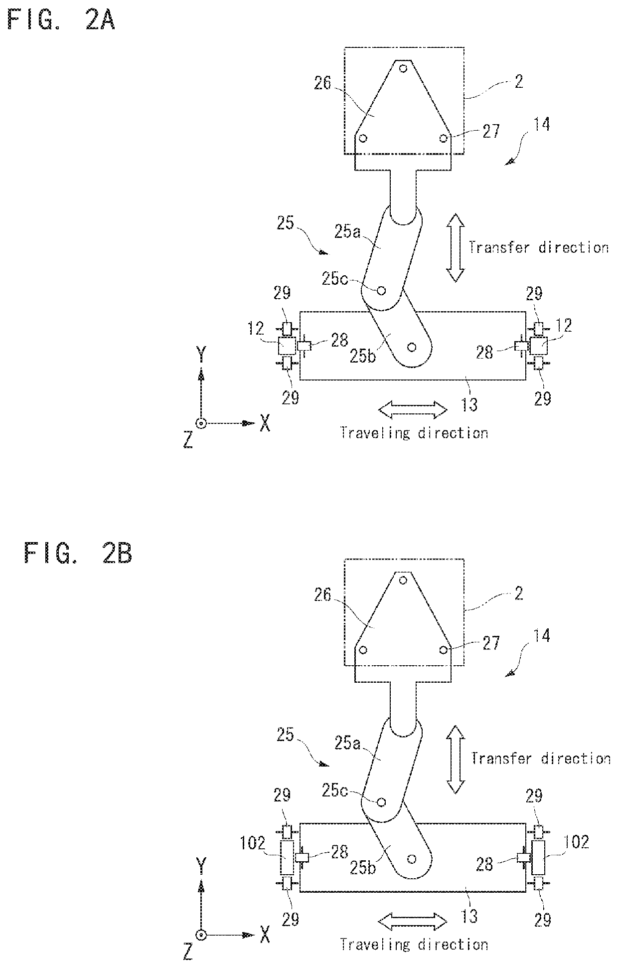
[0075]The transport system 1B of the present preferred embodiment includes a track 41, lower masts 212 different in length from the lower masts 112 described above, and a support 42. As with the track 4, the track 41 allows the traveling body 11 to travel thereon. The track 41 is provided at a height from the floor surface 6 different from that height of the track 4 and is arranged below the track 4 in FIG. 8. As with the track 4, the track 41 may be...

third preferred embodiment

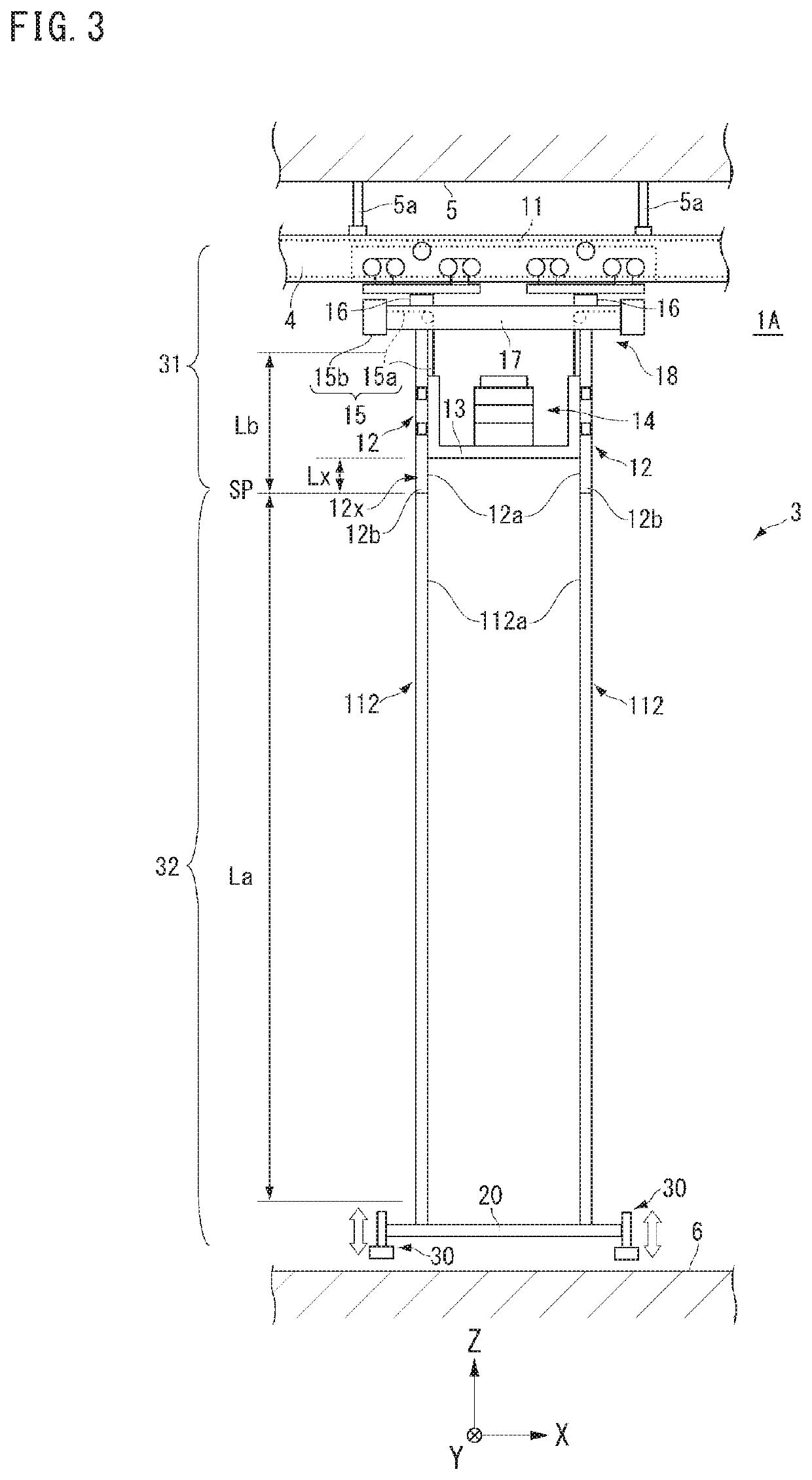
[0082]A third preferred embodiment of the present invention is described. FIG. 12 is a diagram showing an example of an overhead transport vehicle 3A related to the third preferred embodiment. In the present preferred embodiment, similar members as those described above are assigned with the same symbols and the descriptions thereof are omitted or simplified. As shown in FIG. 12, in the overhead transport vehicle 3A, the upper masts 12 are attached to the upper support body 17 via connectors 18. Each connector 18 is, for example, a hinge, and has a horizontal direction (Y direction) axis center orthogonal to the traveling direction (the X direction) of the traveling body 11. Each connector 18 transmits almost no moment about the axis center thereof when friction is ignored. The traveling body 11 supports the upper masts 12 by the connectors 18 each having a mechanism capable of rotating (freely rotating) about the axis center.

[0083]The connectors 18 each receive a moment about two d...


PUM


Abstract

An overhead transport vehicle includes a traveling body that travels on a track on a ceiling of a facility, an upper mast attached to a lower side of the traveling body and including an upper guide, an elevation platform on which an article is placed, and which is guided by the upper guide to ascend or descend along the upper mast, and a lift driver that is provided on the traveling body or on the elevation platform and that drives the elevation platform to ascend or descend A lower mast is connected to the lower end of the upper mast via a connector in a freely detachable manner and includes a lower guide extending to the upper guide. The elevation platform is able to be lowered along the lower mast from the upper mast by the lift driver.

Description

BACKGROUND OF THE INVENTION1. Field of the Invention[0001]The present invention relates to an overhead transport vehicle and a transport system.2. Description of the Related Art[0002]In an automated warehouse or in an intra-bay facility or the like where a processing apparatus is arranged therein, a stacker crane or the like is used for transferring articles (for example, refer to Japanese Patent No. 5545498). The stacker crane of Japanese Patent No. 5545498 includes a traveling body that travels and moves while being guided by a floor side track, a plurality of masts erected on the traveling body, a guided part that is guided by a ceiling side track, and an elevation platform that ascends or descends along the masts.[0003]In the stacker crane of Japanese Patent No. 5545498, a lower portion and an upper portion of the masts can be freely separated from or connected to each other. When a maintenance work is carried out, the masts are separated into a lower portion and an upper portio...

Claims


Application Information

Patent Timeline
Patent Type & Authority Applications(United States)
IPC IPC(8): B65G1/04
CPCB07C5/36B65G1/0428B08B5/023B65G1/10B66F9/08B65G1/0492B65G1/0407B65G2201/0297B66F9/07H01L21/67706H01L21/67733H01L21/67736H01L21/6773
Inventor TANAKA, HIROSHI
Owner MURATA MASCH LTD
Why Eureka
Try Eureka