Propellant container for a perforating gun

a perforating gun and container technology, applied in the field of perforating gun propulsion containers, to achieve the effect of altering the deflagration rate of one or more pieces

Active Publication Date: 2019-06-27
THE GASGUN LLC
View PDF4 Cites 0 Cited by
  • Summary
  • Abstract
  • Description
  • Claims
  • Application Information

AI Technical Summary

Benefits of technology

[0004]Embodiments disclosed herein include a propellant container for a perforating gun that includes a lower cap, one or more pieces of propellant positioned within the lower cap, wherein at least one of the one or more pieces of propellant defines one or more through-holes, an upper cap matable with the lower cap to secure the one or more pieces of propellant within the lower cap, and a filler material present within interstitial spaces between the one or more pieces of propellant. In a further embodiment, the propellant container may include wherein the upper and lower caps exhibit a cross-sectional shape selected from the group consisting of circular, polygonal, oval, ovoid, and any combination thereof. In another further embodiment of any of the previous embodiments, the propellant container may further include wherein the upper and lower caps are made of a material selected from the group consisting of cardboard, wood, paper, a polymer, a composite material, a metal, and any combination thereof. In another further embodiment of any of the previous embodiments, the propellant container may further include wherein the one or more pieces of propellant are cylindrical and exhibit a cross-sectional shape selected from the group consisting of circular, polygonal, frustoconical, and any combination thereof. In another further embodiment of any of the previous embodiments, the propellant container may further include wherein the filler material comprises a material selected from the group consisting of sand, a ceramic material, a resin, bauxite, a glass material, a polymer material, a Teflon® material, nut shell pieces, cured resinous particulates comprising nut shell pieces, seed shell pieces, cured resinous particulates comprising seed shell pieces, fruit pit pieces, cured resinous particulates comprising fruit pit pieces, wood, composite particulates, and any combination thereof. In another further embodiment of any of the previous embodiments, the propellant container may further include wherein the filler material is packed tightly into the lower cap and thereby secures the one or more pieces of propellant in place. In another further embodiment of any of the previous embodiments, the propellant container may further include wherein a gap is formed between at least two of the one or more pieces of propellant and the filler material is packed into the gap and separates the at least two of the one or more pieces of propellant. In another further embodiment of any of the previous embodiments, the propellant container may further include wherein the one or more pieces of propellant are non-uniform in dimension. In another further embodiment of any of the previous embodiments, the propellant container may further include wherein the one or more pieces of propellant are non-uniformly positioned within the lower cap. In another further embodiment of any of the previous embodiments, the propellant container may further include wherein at least one of the one or more through-holes is defined through a sidewall of the at least one of the one or more pieces of propellant. In another further embodiment of any of the previous embodiments, the propellant container may further include wherein a rate of combustion of each piece of propellant increases at a greater than linear rate and a surface area of each piece of propellant increases during combustion until consumed by the combustion.
[0005]Embodiments disclosed herein include a perforating gun that includes a charge tube, one or more shaped charges supported in the charge tube, one or more containers supported in the charge tube, wherein each container comprises a lower cap having one or more pieces of propellant positioned therein and at least one of the one or more pieces of propellant defining one or more through-holes, an upper cap matable with the lower cap to secure the one or more pieces of propellant within the lower cap, and a filler material present within interstitial spaces between the one or more pieces of propellant. The perforating gun further includes a detonating cord extending to each shaped charge and each container to ignite the one or more shaped charges and the one or more pieces of propellant in each container, wherein a rate of combustion of each piece of propellant increases at a greater than linear rate and a surface area of each piece of propellant increases during combustion until consumed by the combustion. In a further embodiment, the perforating gun may include a sealed carrier that receives the charge tube for conveyance into a wellbore. In another further embodiment of any of the previous embodiments, the perforating gun may further include wherein the filler material comprises a material selected from the group consisting of sand, a ceramic material, a resin, bauxite, a glass material, a polymer material, a Teflon® material, nut shell pieces, cured resinous particulates comprising nut shell pieces, seed shell pieces, cured resinous particulates comprising seed shell pieces, fruit pit pieces, cured resinous particulates comprising fruit pit pieces, wood, composite particulates, and any combination thereof. In a further embodiment, the perforating gun may include wherein a gap is formed between at least two of the one or more pieces of propellant and the filler material is packed into the gap and separates the at least two of the one or more pieces of propellant.
[0006]Embodiments disclosed herein include a method of creating and finishing perforations in a hydrocarbon well that includes lowering a perforating gun into the hydrocarbon well, the perforating gun including a charge tube, one or more shaped charges supported in the charge tube, and one or more containers supported in the charge tube, wherein each container comprises a lower cap having one or more pieces of propellant positioned therein and at least one of the one or more pieces of propellant defining one or more through-holes, an upper cap matable with the lower cap to secure the one or more pieces of propellant within the lower cap, and a filler material present within interstitial spaces between the one or more pieces of propellant. The method further includes igniting the one or more shaped charges and the one or more pieces of propellant in each container, shooting from the one or more shaped charges a high velocity jet of metal particles through a wall of the hydrocarbon well and thereby creating a perforation, combusting each piece of the propellant at a greater than linear combustion rate and thereby generating a gas that is injected into the perforation, and creating with the gas one or more fissures extending radially from the perforation. In a further embodiment, the method may include increasing a surface area of the one or more pieces of propellant during combustion until consumed by the combustion. In another further embodiment of any of the previous embodiments, the method may further include aerosolizing the filler material into the gas as the one or more pieces of propellant combust, injecting the filler material into the one or more fissures simultaneously with the gas, and propping open the one or more fissures with the filler material. In another further embodiment of any of the previous embodiments, the method may further include selectively altering a deflagration rate of the one or more pieces of the propellant by packing the filler material within a gap formed between at least two of the one or more pieces of propellant to separate the at least two of the one or more pieces of propellant. In another further embodiment of any of the previous embodiments, the method may further include wherein lowering the perforating gun into the hydrocarbon well comprises positioning the charge tube within a sealed carrier and lowering the sealed carrier into the hydrocarbon well.

Problems solved by technology

Unfortunately, the resultant perforation has some characteristics that inhibit the flow of liquid or gas into the perforation from the surrounding rock.

Method used


Image

  • Propellant container for a perforating gun
  • Propellant container for a perforating gun
  • Propellant container for a perforating gun

Examples


Embodiment Construction

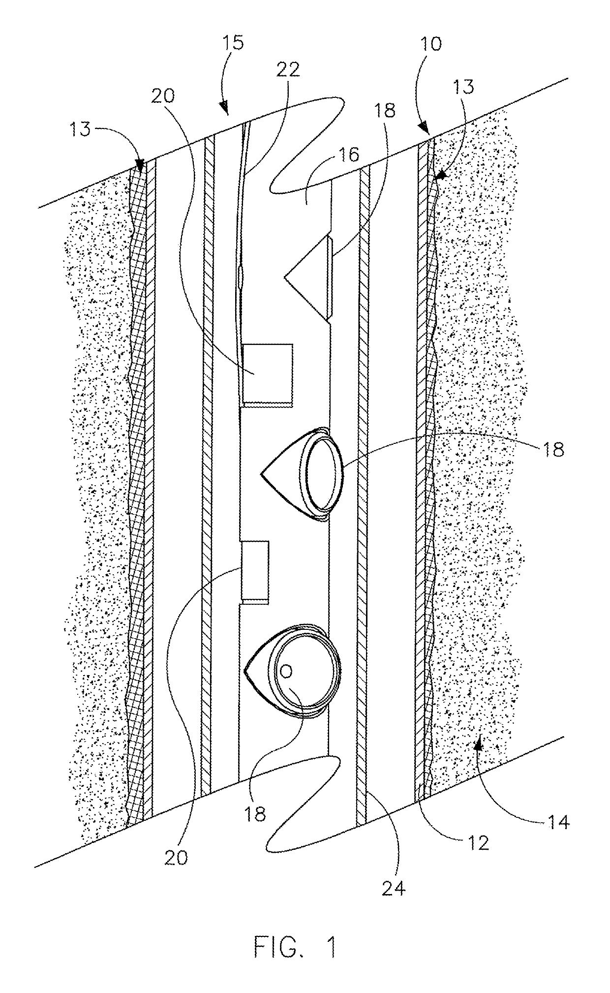
[0021]Referring to FIG. 1, in a preferred method of creating finished perforations in the wall 10 of an oil or gas well, which is made up of steel casing 12, cement 13 and underlying rock 14, a perforating gun 15 is lowered into proximity of a portion of wall 10 to be treated. Perforating gun 15 includes a charge tube 16, which supports a number of shaped charges 18, containers 20 of propellant 38 (FIG. 7) and a detonating cord 22, all encased in a fluid-impermeable sealed steel carrier 24.

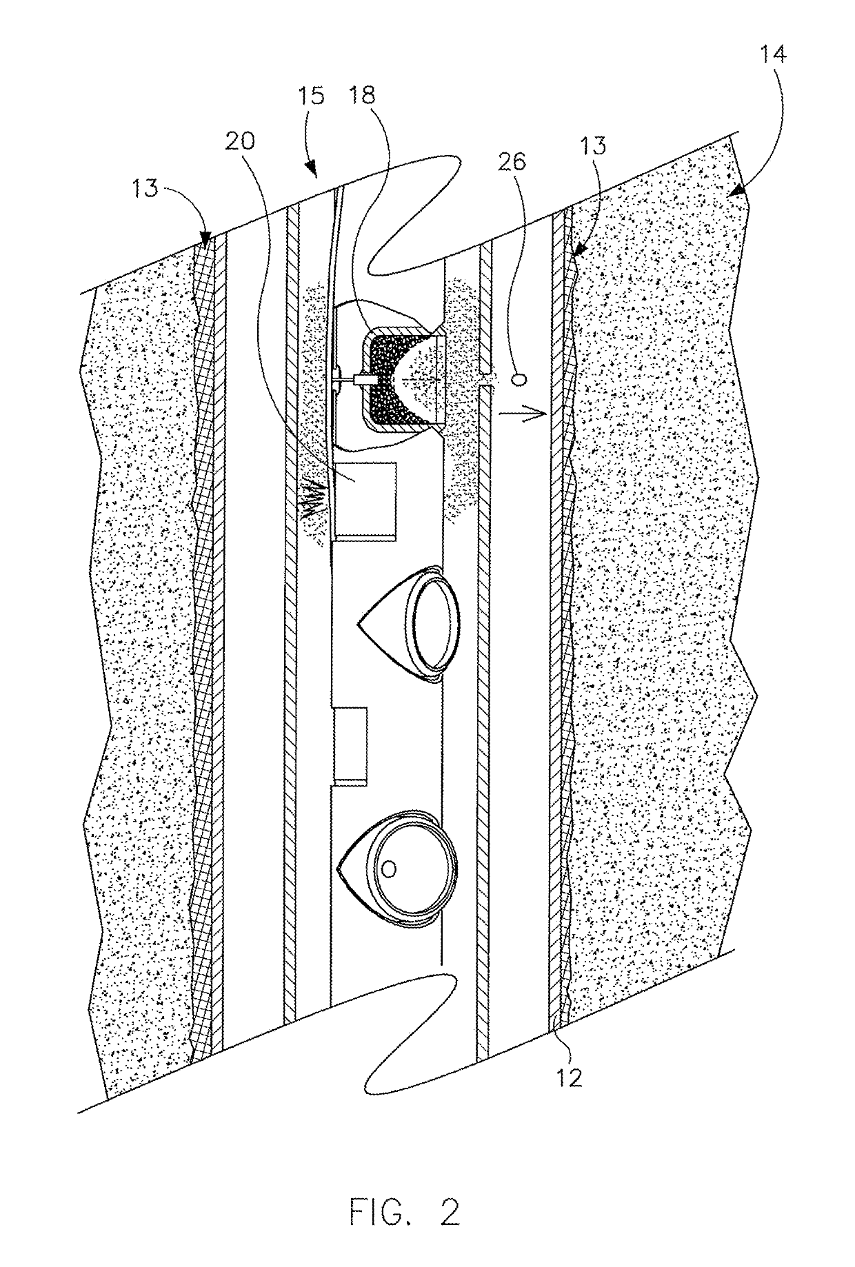
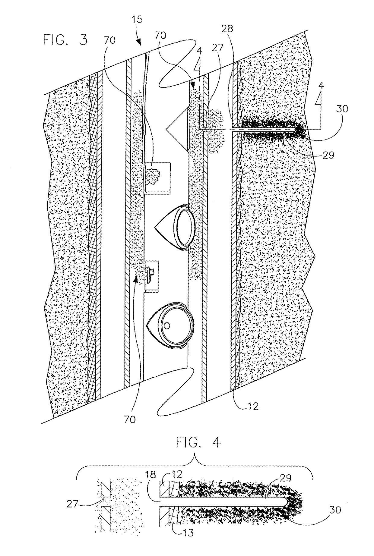
[0022]Referring to FIGS. 2 and 3, the detonating cord 22 is ignited, causing the shaped charges 18 to expel particles of metal 26 (FIG. 2—shown as an ellipse for ease of presentation) at a high velocity, within ten microseconds. Travelling at approximately 30 Mach, the metal particles 26 penetrate through steel carrier 24, creating a carrier perforation 27 (FIG. 3) and into the wall 10, creating a perforation 28 (FIG. 3) through the steel casing 12, and a further perforation 29 (FIG. 3) in the roc...


PUM

PropertyMeasurementUnit
shapeaaaaaaaaaa
dimensionaaaaaaaaaa
surface areaaaaaaaaaaa

Abstract

A propellant container for a perforating gun includes a lower cap, one or more pieces of propellant positioned within the lower cap, wherein at least one of the one or more pieces of propellant defines one or more through-holes, and an upper cap matable with the lower cap to secure the one or more pieces of propellant within the lower cap. A filler material is present within interstitial spaces between the one or more pieces of propellant.

Description

BACKGROUND[0001]This application is a continuation-in-part application claiming priority to U.S. Non-Provisional patent application Ser. No. 16 / 036,920, filed on Jul. 16, 2018, and which is a continuation of U.S. Pat. No. 10,024,145, filed on Dec. 30, 2014.BACKGROUND[0002]A hydrocarbon well (oil or gas) is typically finished using a device known as a perforating gun. This device includes a steel tube containing a set of devices, typically referred to as “shaped charges” each of which includes a charge of high explosive and a small amount of copper. The tube is lowered into the well, and the high explosive charges are detonated, fragmenting the copper and accelerating the resultant copper particles to a speed on the order of 30 Mach, so that it blasts through the wall of the steel tube, through any steel casing forming the wall of the well, and perforates the surrounding rock, thereby permitting oil or gas or both to flow into the well.[0003]Unfortunately, the resultant perforation h...

Claims


Application Information

Patent Timeline
Patent Type & Authority Applications(United States)
IPC IPC(8): E21B43/117E21B43/114
CPCE21B43/117E21B43/114E21B43/11F42B3/00F42B3/02F42B3/04F42B3/22F42D1/043F42D1/045Y10T29/49826
Inventor SCHMIDT, ADAM C.SCHMIDT, JAIA D.SCHMIDT, RICHARD A.
Owner THE GASGUN LLC
Why Eureka
Try Eureka