Method and system for assessing engine faults

a diesel engine and fault technology, applied in the direction of machines/engines, electrical control, exhaust treatment electric control, etc., can solve the problems of not properly accounting for the type of load, most techniques for measuring soot loading in a dpf, dpf, etc., to reduce the amount of available air, and generate high soot levels

Active Publication Date: 2021-07-06
VOLVO LASTVAGNAR AB
View PDF11 Cites 0 Cited by
  • Summary
  • Abstract
  • Description
  • Claims
  • Application Information

AI Technical Summary

Benefits of technology

[0004]The soot oxidation model will ordinarily not account for engine component failure. For components related to combustion, it is important to know the actual status of the components to ensure that excessive soot production does not occur. For example, a broken injector can put extra raw fuel into the exhaust system which can produce excessive soot or face plugging of a DOC. A boost air system malfunction such as a broken turbocharger or a leak in the piping for the boost air reduces the available combustion air, which generates high soot levels. A malfunctioning exhaust gas recirculation (EGR) system can also reduce the amount of available air for combustion of the fuel and produce excessive soot. In short, there are many engine component malfunctions that can generate excessive rates of soot buildup.
[0005]Excessive soot generation can result in a DPF becoming too full before regeneration occurs, or can result in frequent or incomplete regenerations. Frequent or incomplete regenerations can indicate poisoning of a DOC or a DPF. If a regeneration occurs when the filter is too full (or over full), the heat generated can result in a cracked DPF filter from excessive high temperatures or in extreme cases the rate of heat generation may be so fast and so intense that it will melt the ceramic core of the DPF. In both cases the damaged DPF will allow soot to escape the filter into the atmosphere. The escaping soot may also damage the SCR downstream of the DPF. It is important to prevent the DPF from being damaged to avoid damage and other subsequent expensive repairs.
[0008]It is desirable to provide an improved technique for assessing whether detected possible engine component faults are actual faults or false warnings. It is also desirable to prevent avoidable failure of DPFs by early detection of excessive soot loading.

Problems solved by technology

Most techniques for measuring soot loading in a DPF, such as techniques relying on pressure drop across a DPF, are notoriously imprecise and do not properly account for the type of loading.
For example, whether the loading involves substrate surface loading of pores or plugging of pores can significantly impact the actual loading of the DPF.
Excessive soot production, often the result of malfunction of combustion related engine components, may not be detected by these techniques, or may not be detected in a sufficiently timely manner.
The pressure drop method also cannot distinguish between soot loading or ash loading.
The soot oxidation model will ordinarily not account for engine component failure.
For example, a broken injector can put extra raw fuel into the exhaust system which can produce excessive soot or face plugging of a DOC.
A boost air system malfunction such as a broken turbocharger or a leak in the piping for the boost air reduces the available combustion air, which generates high soot levels.
A malfunctioning exhaust gas recirculation (EGR) system can also reduce the amount of available air for combustion of the fuel and produce excessive soot.
In short, there are many engine component malfunctions that can generate excessive rates of soot buildup.
Excessive soot generation can result in a DPF becoming too full before regeneration occurs, or can result in frequent or incomplete regenerations.
If a regeneration occurs when the filter is too full (or over full), the heat generated can result in a cracked DPF filter from excessive high temperatures or in extreme cases the rate of heat generation may be so fast and so intense that it will melt the ceramic core of the DPF.
The escaping soot may also damage the SCR downstream of the DPF.
Significantly higher loads than expected or fast load rate increases are generally a result of engine component failures.
Higher loads, but not necessarily significantly higher loads, and slower rate increases are generally a result of component deterioration and system drift.
Engine malfunction due to faulty components can also result in a high soot output condition.
There are many engine malfunctions which can generate excessive rates of soot buildup which the soot oxidation model cannot capture and existing DPF soot sensors do not respond fast enough to prevent DPF damage.
Consequently, it is not infrequent that DPF are regenerated with incorrect soot loading information, which can cause high heat conditions and broken DPFs.
Further, notifications of software function controllability failure for components such as EGR and turbocharger systems can be indicative of a component failing to respond properly to a control command.
While it is important to know the functional status of engine components, it is not uncommon for fault signals to be false warnings, such as due to poor calibration or poorly designed software diagnostic functions.
Additionally, many diagnostics tools diagnose problems from an “inferred” point of view, i.e. other measureable engine effects are observed as they relate to a component's operation and, if the effects do not follow the component's changes in some way, a fault may be diagnosed.
Such inferred diagnostic arrangements often result in intermittent fault signals and go back and forth from indicating a fault to not indicating a fault until there is sufficient failure to more definitively diagnose a problem.
Accordingly, warnings to which attention should be paid may be ignored and may result in excessive soot production, while false warnings may be heeded and unnecessary servicing may be undertaken.

Method used


Image

  • Method and system for assessing engine faults
  • Method and system for assessing engine faults
  • Method and system for assessing engine faults

Examples


Embodiment Construction

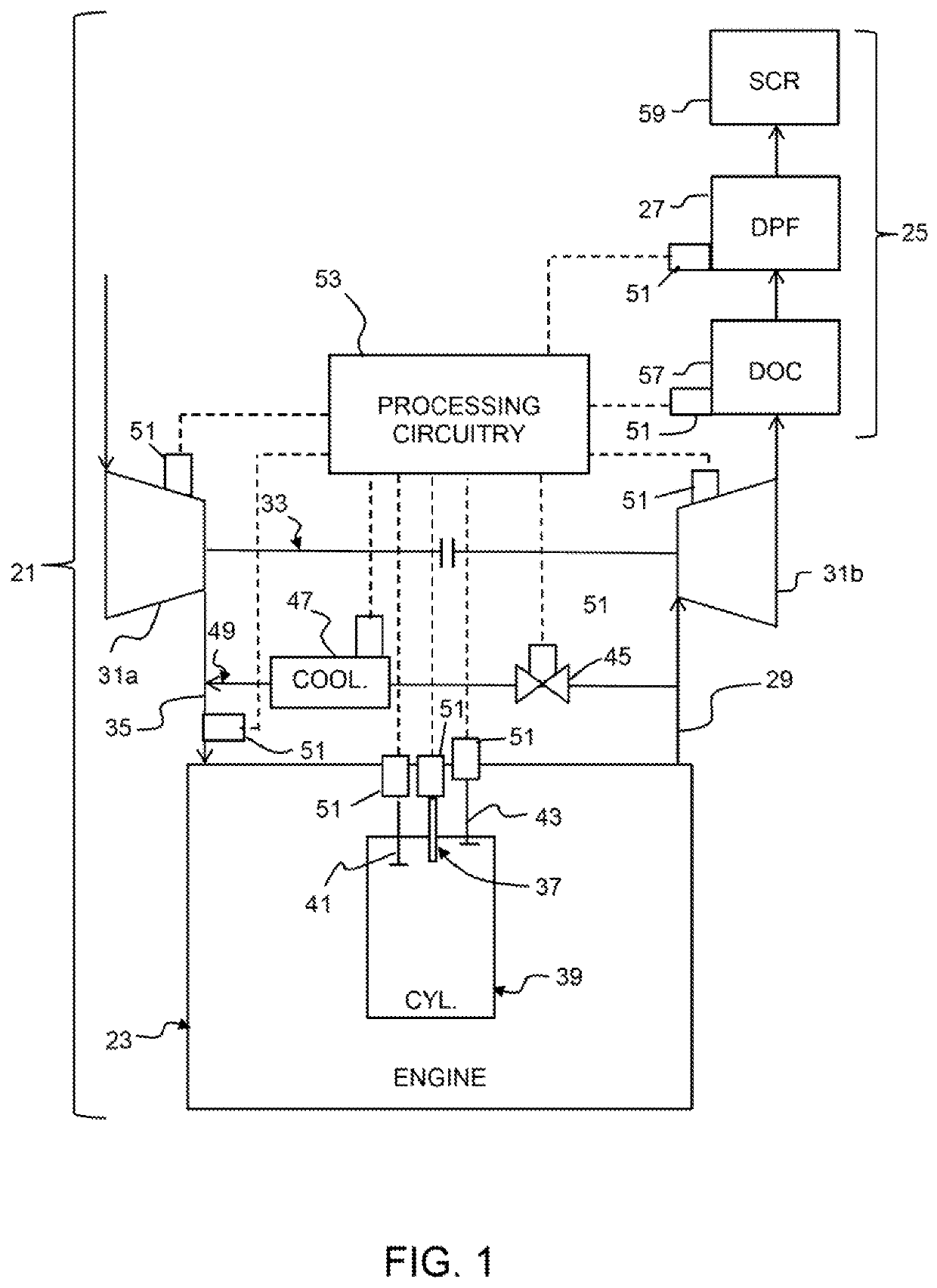
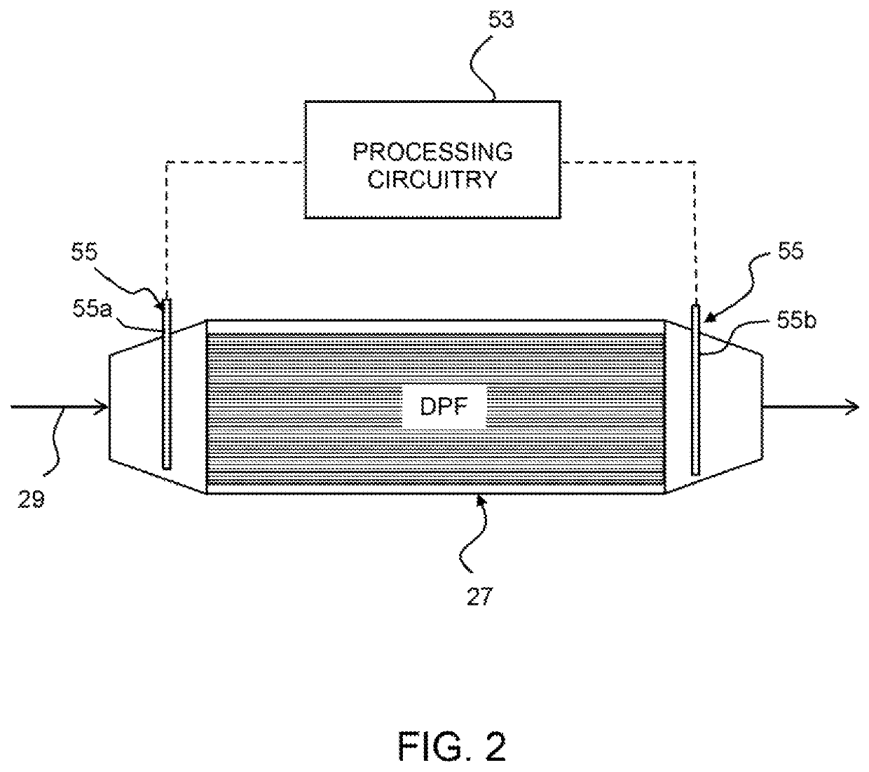
[0017]A system 21 for assessing engine faults is shown in FIG. 1. The system 21 is used in conjunction with a diesel engine 23 comprising an exhaust after-treatment system 25 (EATS) that includes a DPF 27 in an exhaust line 29 downstream of the engine. The EATS 25 will ordinarily include other components, as well, such as a diesel oxidation catalyst 57 (DOC) and a selective catalytic reduction catalyst 59 (SCR). It is presently anticipated that the system will be primarily of use for assessing the severity of functional faults relating to the functioning of components involved in combustion, such as, but not limited to, functioning of compressors 31a (such as in a variable geometry turbocharger 33 comprising an associated turbine 31b in the exhaust line 29) for providing boost pressure in an intake line 35 upstream of the engine 23, fuel injectors 37 for providing fuel to cylinders 39 of the engine, timing of opening of cylinder intake valves 41 and cylinder exhaust valves 43 for co...


PUM


Abstract

A method and system are provided for assessing engine faults. The method includes measuring actual diesel particulate filter (DPF) soot loading, determining expected DPF soot loading, aid determining that a possible engin component fault is an actual engine component fault by determining that measured actual DPF soot loading exceeds the expected DPF soot loading.

Description

BACKGROUND AND SUMMARY[0001]The present invention relates generally to methods and systems for assessing diesel engine faults and, more particularly, to assessing diesel engine faults based on diesel particulate filter (DPF) soot loading.[0002]Modern diesel engines are typically provided with exhaust aftertreatment systems (EATS). A typical EATS will include diesel oxidation catalyst (DOC), a DPF, and a selective catalytic reduction catalyst (SCR). Soot loading in the DPF is typically determined by a soot oxidation model embodied in processing circuitry and based on extensive testing of the engine model in question under various operating and load conditions. Soot loading in the DPF is also typically measured by techniques such as determining the pressure drop across the DPF. When the soot oxidation model or soot loading measurement techniques determine that the soot loading of the DPF has reached a predetermined level, a regeneration will be performed.[0003]Most techniques for meas...

Claims


Application Information

Patent Timeline
Patent Type & Authority Patents(United States)
IPC IPC(8): F01N9/00F02D41/02F01N3/023
CPCF01N9/002F02D41/029F01N3/023F01N2560/05F01N2900/1606F02D2200/0812F01N3/021F01N11/00F02D41/22F01N9/005F02D41/1467F02D41/1466Y02T10/12Y02T10/40
Inventor GEYER, STEPHENHOOVER, DALE
Owner VOLVO LASTVAGNAR AB
Why Eureka
Try Eureka