Cleaning appliance

a technology for cleaning appliances and dust separators, which is applied in the direction of cleaning equipment, suction handles, suction filters, etc., can solve the problems of reducing the likelihood of accidental removal of bins during use, and the bins cannot be removed from the dirt separator, so as to achieve a more hygienic dirt emptying procedure

Active Publication Date: 2019-07-04
DYSON TECH LTD
View PDF0 Cites 12 Cited by
  • Summary
  • Abstract
  • Description
  • Claims
  • Application Information

AI Technical Summary

Benefits of technology

[0009]The bin may comprise a bin lid hingedly attached to the side wall of the bin, and the bin lid is pivotably movable between a closed position in which dirt is retained in the bin and an open position in which dirt can escape the bin. This allows for easy emptying of dirt from the bin.
[0010]A bin lid ...

Problems solved by technology

As a result, the bin can only be removed from the cleaning appliance once the bin has been moved into the extended position from the operational position, reducing the likelihood ...

Method used


Image

  • Cleaning appliance
  • Cleaning appliance
  • Cleaning appliance

Examples


Embodiment Construction

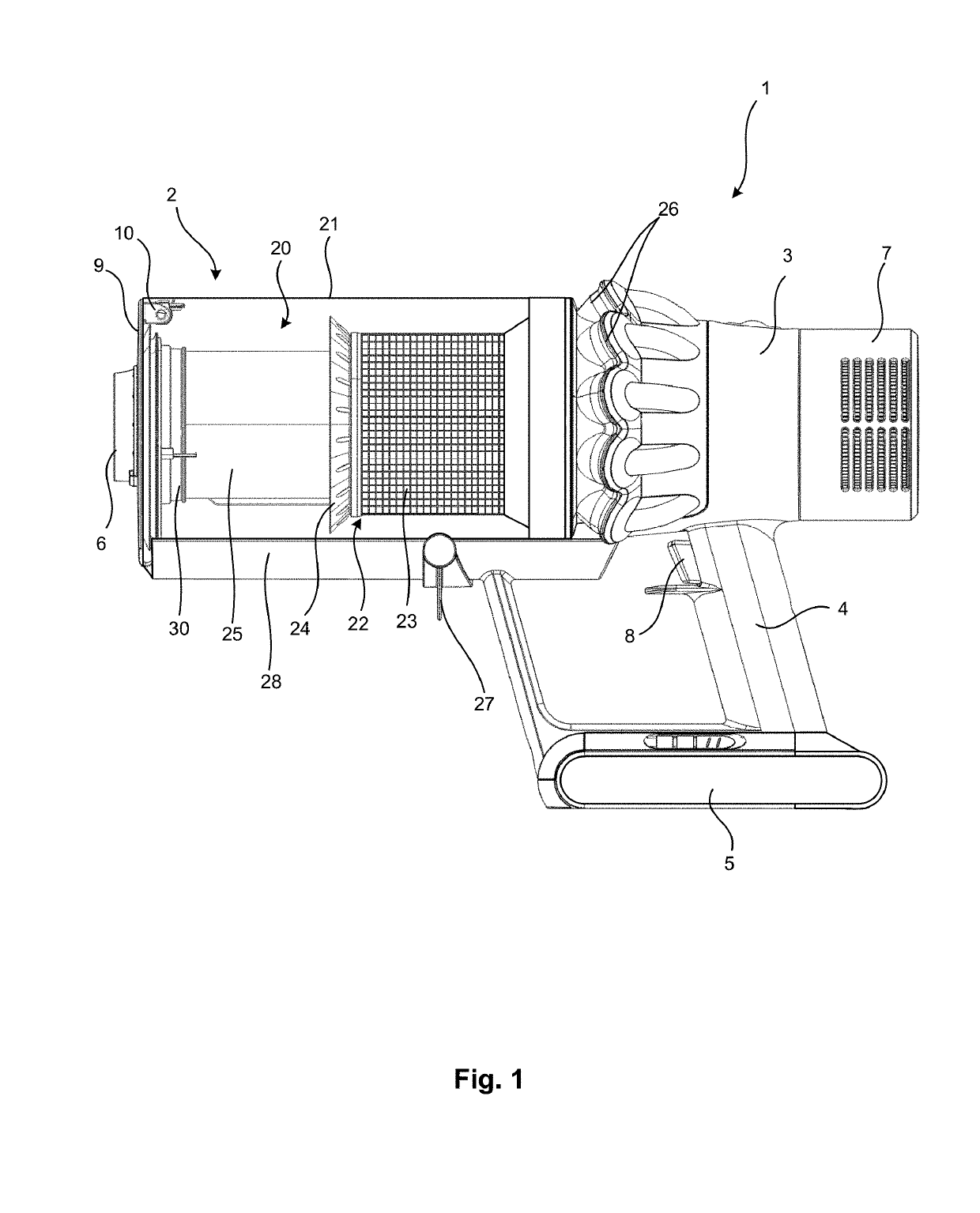
[0017]FIG. 1 shows a cleaning appliance in the form of a handheld vacuum cleaner 1 having a dirt separator 2, a main body 3, a handle 4, a power source in the form of battery pack 5, and an inlet 6. The main body 3 comprises a runner portion 28 which supports the dirt separator 2. At the rear of the vacuum cleaner 1, attached to the main body 3, is a filter assembly 7. The vacuum cleaner 1 is operated by the trigger 8 in the handle 4.

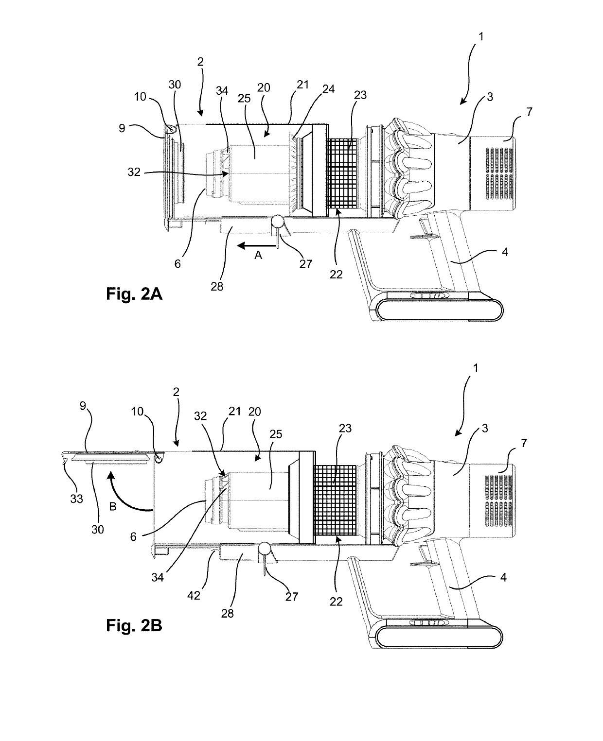
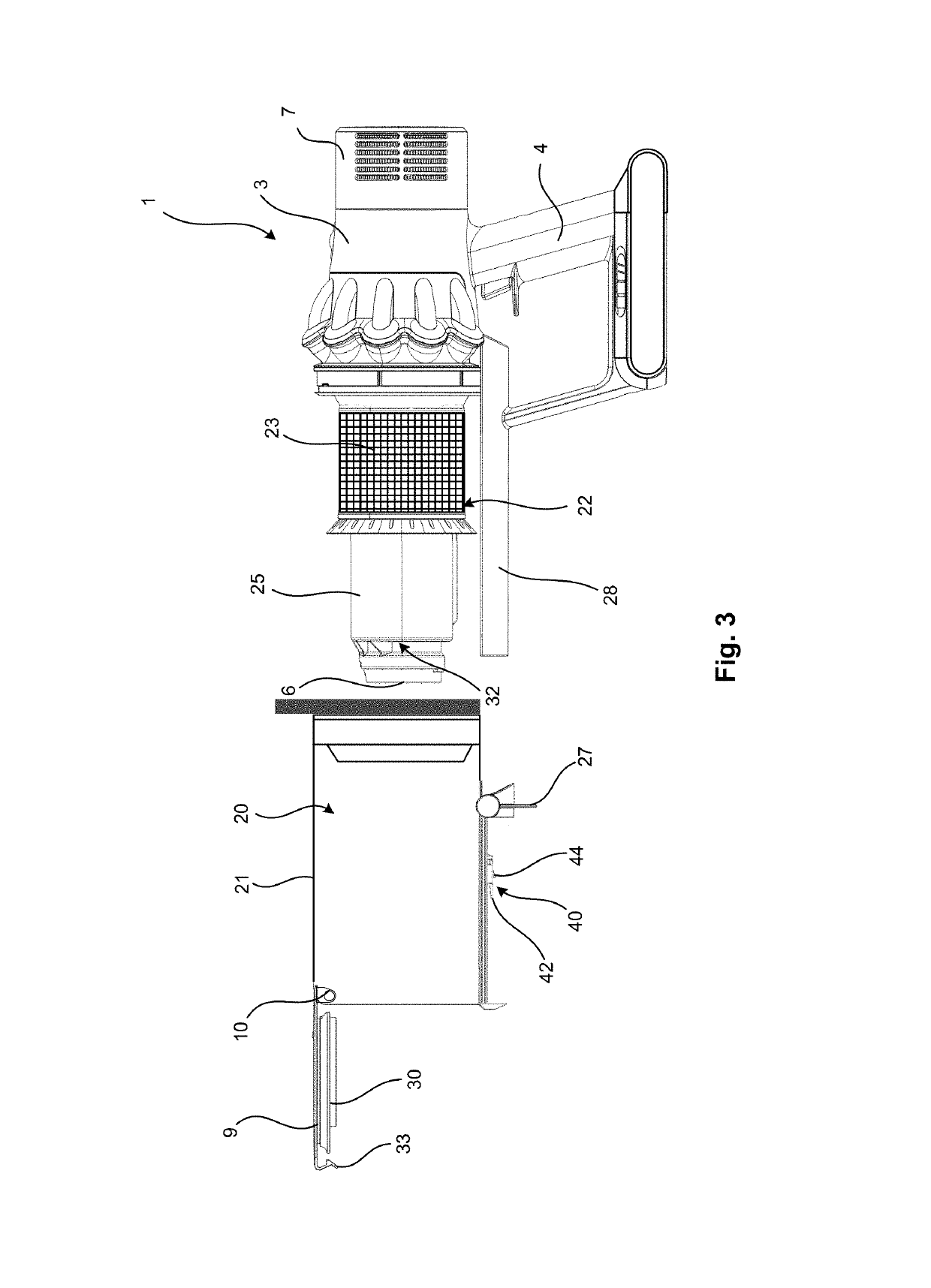
[0018]The dirt separator 2 has a first separation stage and a second separation stage. The first separation stage comprises a cylindrical outer wall 21 which defines a bin 20. In FIG. 1 the bin 20 is in an operational position. A cylindrical inner wall 25 defines a fine dust collection chamber which is positioned inside the bin 20. A closure member in the form of a bin lid 9 is hingedly attached to the outer wall 21 of the dirt separator 2 at hinge 10. The bin lid 9 is pivotable about the hinge 10 between an open position in which dust and dirt can esca...


PUM


Abstract

A cleaning appliance includes a dirt separator for separating dirt from an airflow, and a main body, the dirt separator including a bin for collecting dirt separated from the airflow, and the main body including a runner portion extending alongside a side wall of the bin, wherein the bin is slidable along the runner portion between an operational position and an extended position, and a release catch releasably engages with a formation on the runner portion to prevent the bin from being separated from the cleaning appliance, and wherein the release catch is positioned on the side wall of the bin such that it is hidden by the runner portion of the main body unless the bin is in the extended position.

Description

REFERENCE TO RELATED APPLICATIONS[0001]This application claims the priority of United Kingdom Application No. 1722303.3 filed Dec. 30, 2017, the entire contents of which are incorporated herein by reference.FIELD OF THE INVENTION[0002]The present invention relates to a cleaning appliance.BACKGROUND OF THE INVENTION[0003]Improvements to vacuum cleaners are always being sought. In particular improvements that make it easier for a user to use the vacuum cleaner, and to encourage the user the use the vacuum cleaner in the best way possible. It is desirable to ensure that the user is not able to carry out any operations which could result in a fault that needs to be resolved or requires troubleshooting.SUMMARY OF THE INVENTION[0004]A first aspect of the present invention provides a cleaning appliance comprising a dirt separator for separating dirt from an airflow, and a main body, the dirt separator comprising a bin for collecting dirt separated from the airflow, and the main body compri...

Claims


Application Information

Patent Timeline
IPC IPC(8): A47L9/14A47L9/32A47L9/10
CPCA47L9/1463A47L9/322A47L9/102A47L5/24A47L9/00A47L9/10A47L9/1608A47L9/1683A47L9/1691B04C5/185
Inventor CROUCH, JEREMY WILLIAMISLEY, DAVID ANDREW
Owner DYSON TECH LTD
Why Eureka
Try Eureka