
Hand-held machine tool comprising a dust box

a technology of dust box and hand-held machine tools, which is applied in the direction of manufacturing tools, portable power-driven tools, drilling machines, etc., can solve the problems of high cooling efficiency and uncompromised, and achieve the effects of easy dust removal, convenient emptying, and convenient removal

Inactive Publication Date: 2009-01-13
ROBERT BOSCH GMBH
View PDF14 Cites 15 Cited by
  • Summary
  • Abstract
  • Description
  • Claims
  • Application Information

AI Technical Summary

Benefits of technology

The present invention is a power tool with improved cooling and dust evacuation capabilities. The cooling exhaust air is directed over the dust box, resulting in unthrottled cooling exhaust air and improved dust evacuation. The chip evacuation in the tool engagement region is also improved via the injector action of the cooling exhaust-air flow directed over the dust box. The efficiency of motor cooling is high and uncompromised. The two air streams, dust evacuation and cooling exhaust air, are prevented from mixing, ensuring highly efficient dust evacuation and motor cooling. The dust box includes an air outlet opening for both the dust evacuation and cooling exhaust air, resulting in a marked improvement in dust evacuation. The cooling exhaust air can be easily guided further to the dust box and across its outer surface. The dust box is provided with a base and top wall capable of being detached in the manner of a cover, making it easy to empty and remove the dust. The cooling exhaust-air flow must exit the housing tangentially through a cyclone-like annular exhaust air duct, reducing flow resistance and noise.

Problems solved by technology

Due to the fact that the cooling exhaust air is guided separately from the dust evacuation air away from the housing to the dust box and past it in an unthrottled manner, the efficiency of the motor cooling is high and uncompromised.

Method used


Image

  • Hand-held machine tool comprising a dust box
  • Hand-held machine tool comprising a dust box
  • Hand-held machine tool comprising a dust box

Examples


Embodiment Construction

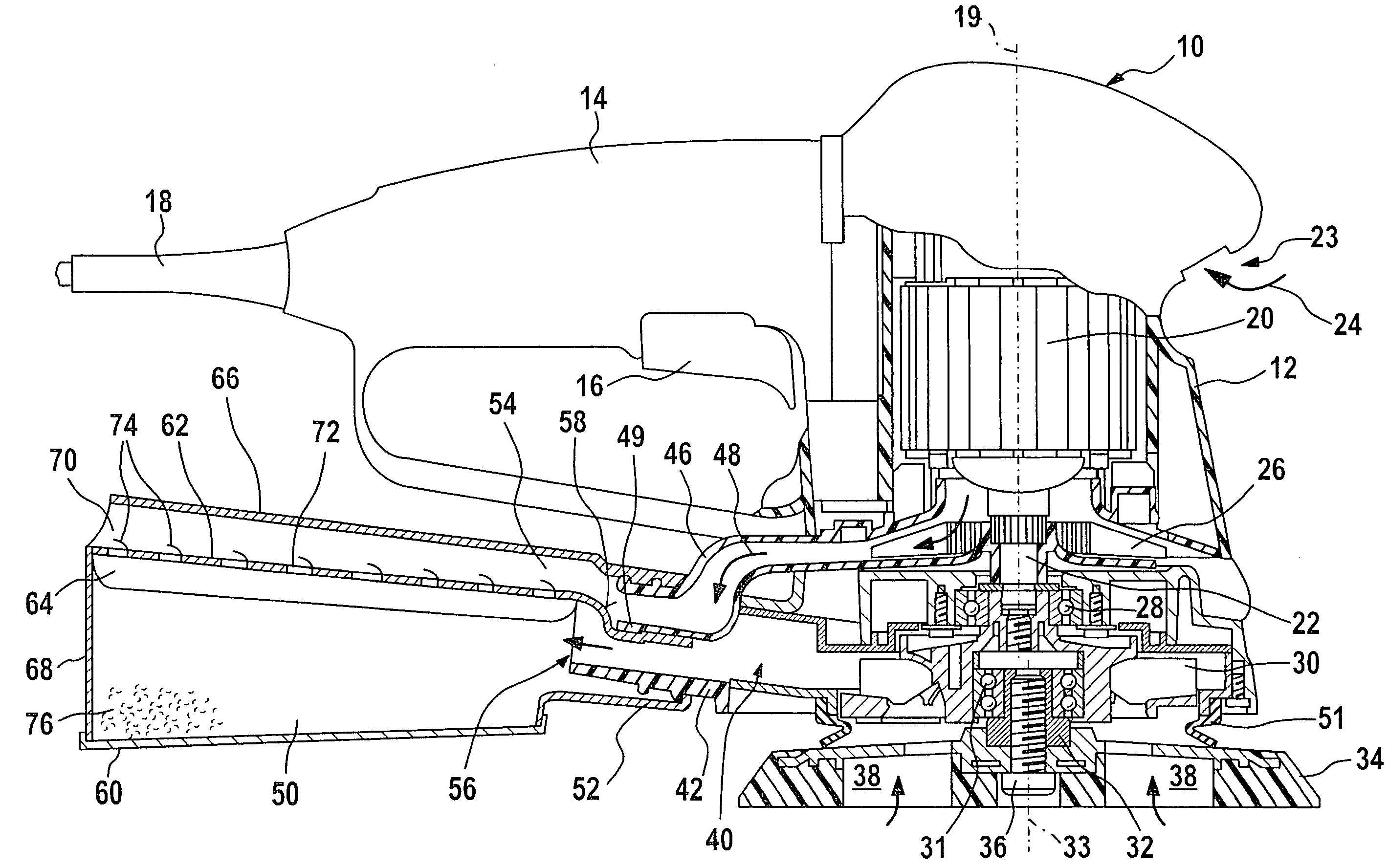
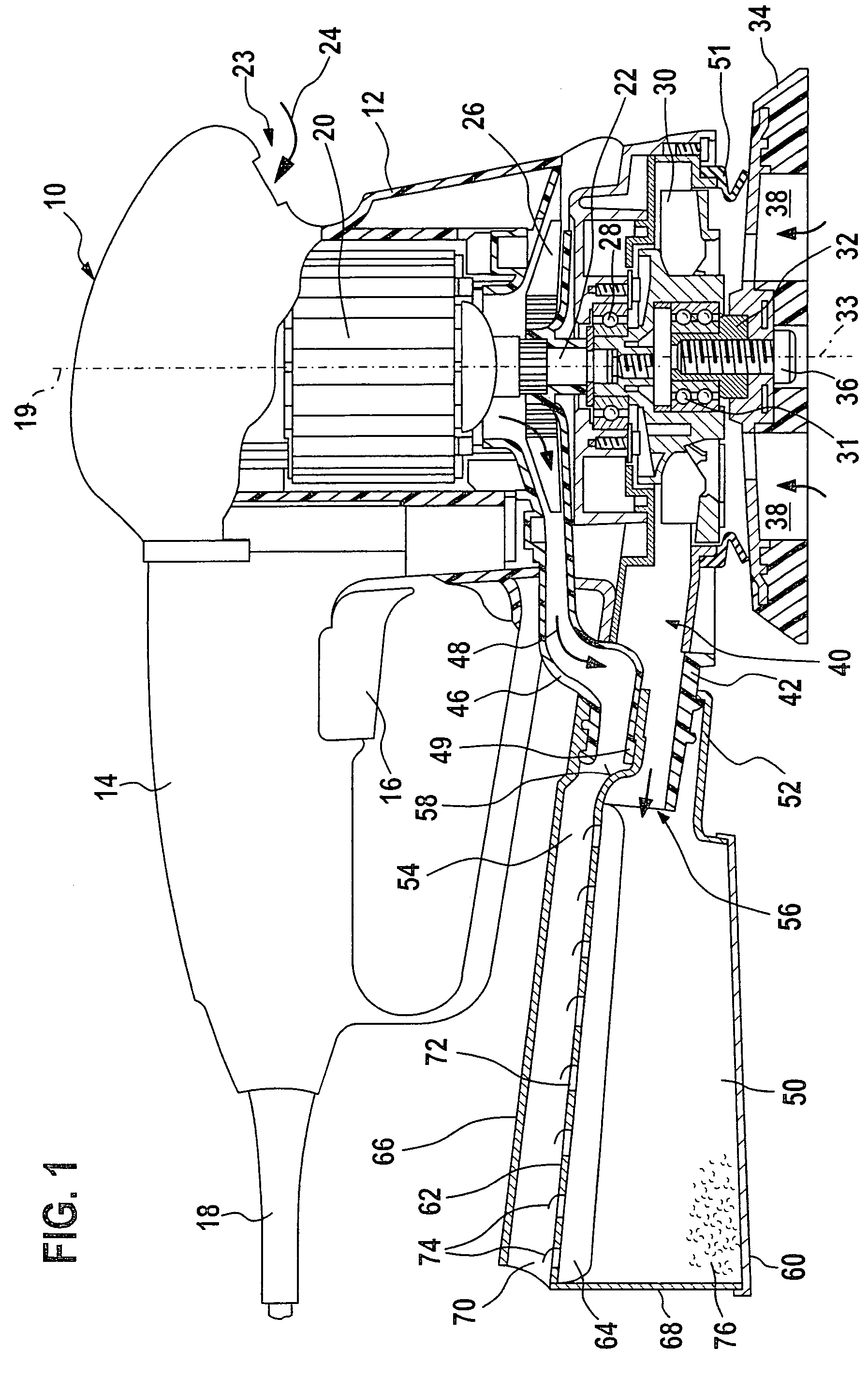
[0019]The drawing shows a power tool 10 designed as a disk-type sander with a housing 12 that has a horizontal handle 14 shown at the left in the drawing, the handle including a manually-operated switching key 16 of a switch (not shown) for starting and stopping motor 20.

[0020]An electric cord 18 extends out of the back end of handle 14, the electric cord providing power to motor 20.

[0021]Housing 12 carries motor 20 with a motor axis 19 extending perpendicularly to handle 14, in the downward extension of which a motor shaft 22 projects out of motor 20. Its end is wrapped-around in a torsion-proof manner by a cooling ventilator 26 that moves air radially outwardly in the direction of arrow 48. As a result, cooling outside air is drawn in via the upper region of housing 12 through cooling slits 23 in housing 12; the cooling outside air can flow into housing 12 as indicated by arrow 24 and past motor 20, and then exit housing 12 via its suction connecting piece 42 through a connecting ...


PUM

PropertyMeasurementUnit
distanceaaaaaaaaaa
surface areaaaaaaaaaaa
resistanceaaaaaaaaaa

Abstract

A power tool (10) with a housing (12) that includes a dust box (50, 150) and a motor (20) with air cooling, and a cooling exhaust-air duct (44, 46) and a chip suctioning duct (40) which guides a chip-suctioning flow can be used with improved performance and in an environmentally friendlier manner due to the fact that the cooling air flows across the dust box (50, 150) under favorable flow conditions, whereby the evacuation of dust into the dust box (50, 150) is improved and whirls of dust caused by cooling air in the tool region are prevented from forming.

Description

CROSS-REFERENCE[0001]The invention described and claimed hereinbelow is also described in PCT / DE 03 / 02668, filed Aug. 7, 2003 and DE 102 54 839.0, filed Nov. 25, 2002. This German Patent Application, whose subject matter is incorporated here by reference, provides the basis for a claim of priority of invention under 35U.S.C. 119 (a)-(d).BACKGROUND OF THE INVENTION[0002]The present invention relates to a power tool with dust box.[0003]A power tool with motor air-cooling is made known in U.S. Pat. No. 4,209,069, the cooling air of which is suctioned through the dust box. A dust filter is located between the dust box and the cooling ventilator to prevent dust from entering the interior of the motor with the cooling air. In addition, a chip suctioning tube extends from the power tool to the dust box. The chips and dust produced when a tool engages in a work piece are transported to the dust box through this tube.[0004]The disadvantage of this is that the cooling air flow is restricted b...

Claims


Application Information

Patent Timeline
Patent Type & Authority Patents(United States)
IPC IPC(8): B23Q11/00B23B45/00B24B55/10B25D17/14B25F5/02
CPCB23Q11/0046
Inventor WUENSCH, STEFFEN
Owner ROBERT BOSCH GMBH
Learn More