Venting unit for a Die Casting device

a technology of die casting device and venting unit, which is applied in the direction of foundry moulds, moulding machine components, foundry moulding apparatus, etc., can solve the problems of only evacuating the mold cavity unsatisfactory, affecting the quality of the casting produced, and impairing the extraction capability, so as to reduce flow losses, improve the evacuation effect, and reduce the flow cross-section

Inactive Publication Date: 2010-11-04
ELECTRONICS GMBH VERTRIEB ELEKTRONISCHER GERATE
View PDF5 Cites 8 Cited by
  • Summary
  • Abstract
  • Description
  • Claims
  • Application Information

AI Technical Summary

Benefits of technology

[0008]This object is achieved according to the invention in the case of a venting unit of the type mentioned at the beginning by the flow cross-section of the flow labyrinth being variable. This provides the possibility of reducing flow losses within the flow labyrinth when gas is extracted from the mold cavity, since a relatively large flow cross-section can be chosen for the flow labyrinth for the extraction of gas from the mold cavity. The evacuation of the mold cavity can be significantly improved as a result. However, to be able to avoid liquid casting material being able to flow through the flow labyrinth and escape from the venting unit, the flow cross-section of the flow labyrinth can be reduced, so that it is ensured that inflowing casting material reliably solidifies within the flow labyrinth.

Problems solved by technology

To avoid air bubbles being trapped in the casting material, which is at first liquid and then hardens in a very short time, with the trapped air bubbles possibly impairing the quality of the casting produced, the air can be extracted from the mold cavity by means of a gas suction device.
The narrow gaps impair the extraction capability.
In many cases it has been found that, even though powerful gas suction devices are provided, the mold cavities are only evacuated unsatisfactorily.

Method used


Image

  • Venting unit for a Die Casting device
  • Venting unit for a Die Casting device
  • Venting unit for a Die Casting device

Examples


Embodiment Construction

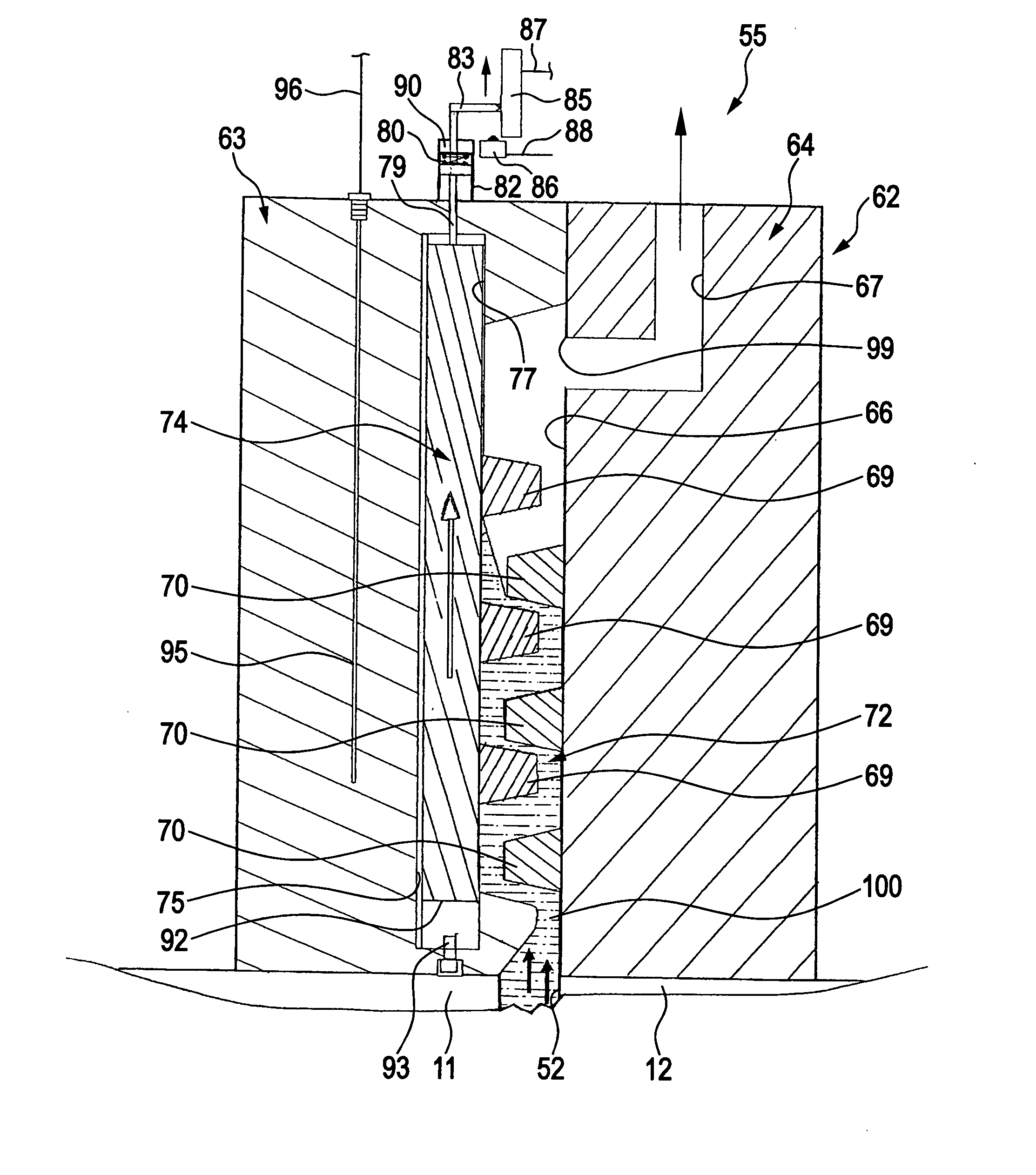
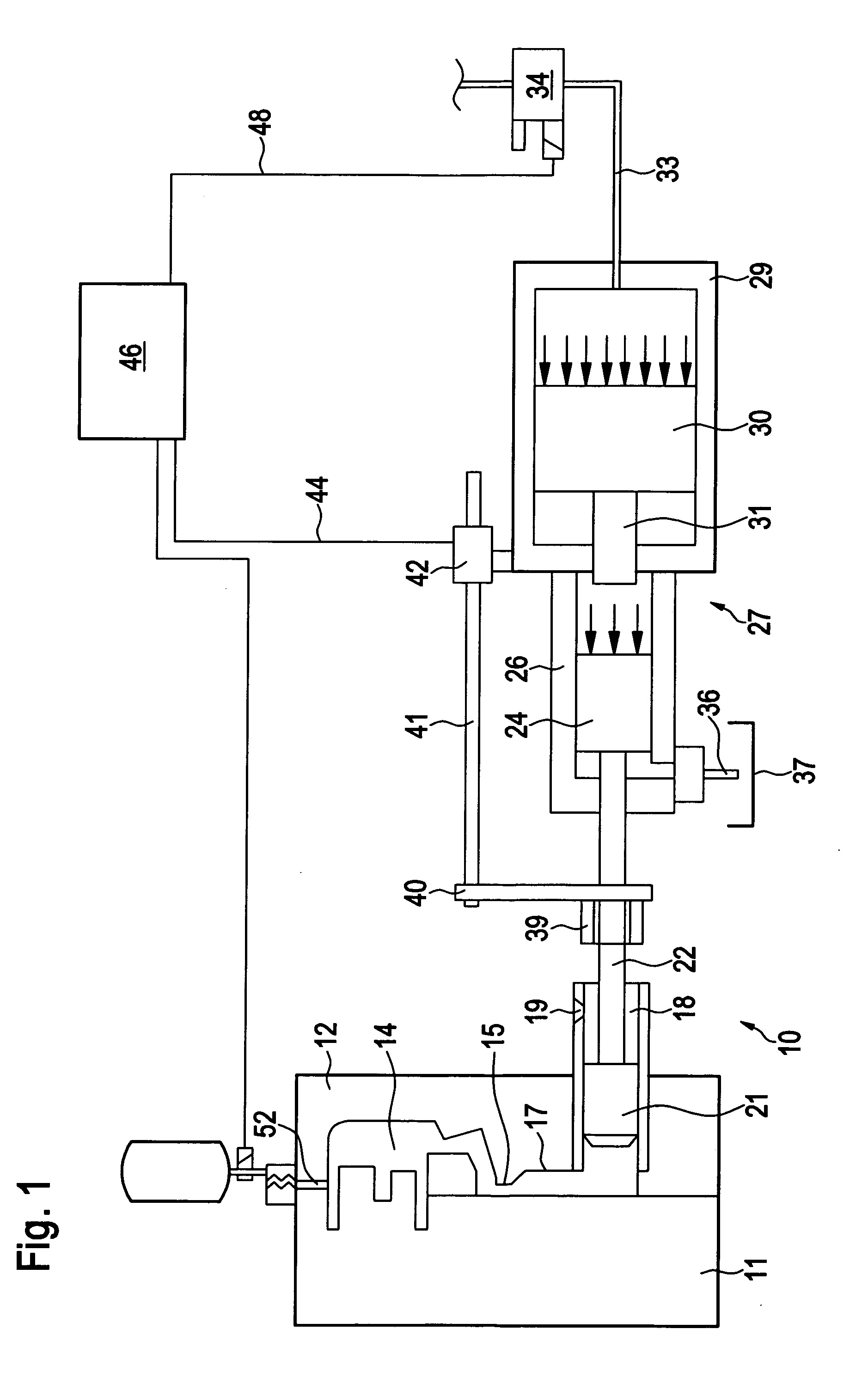
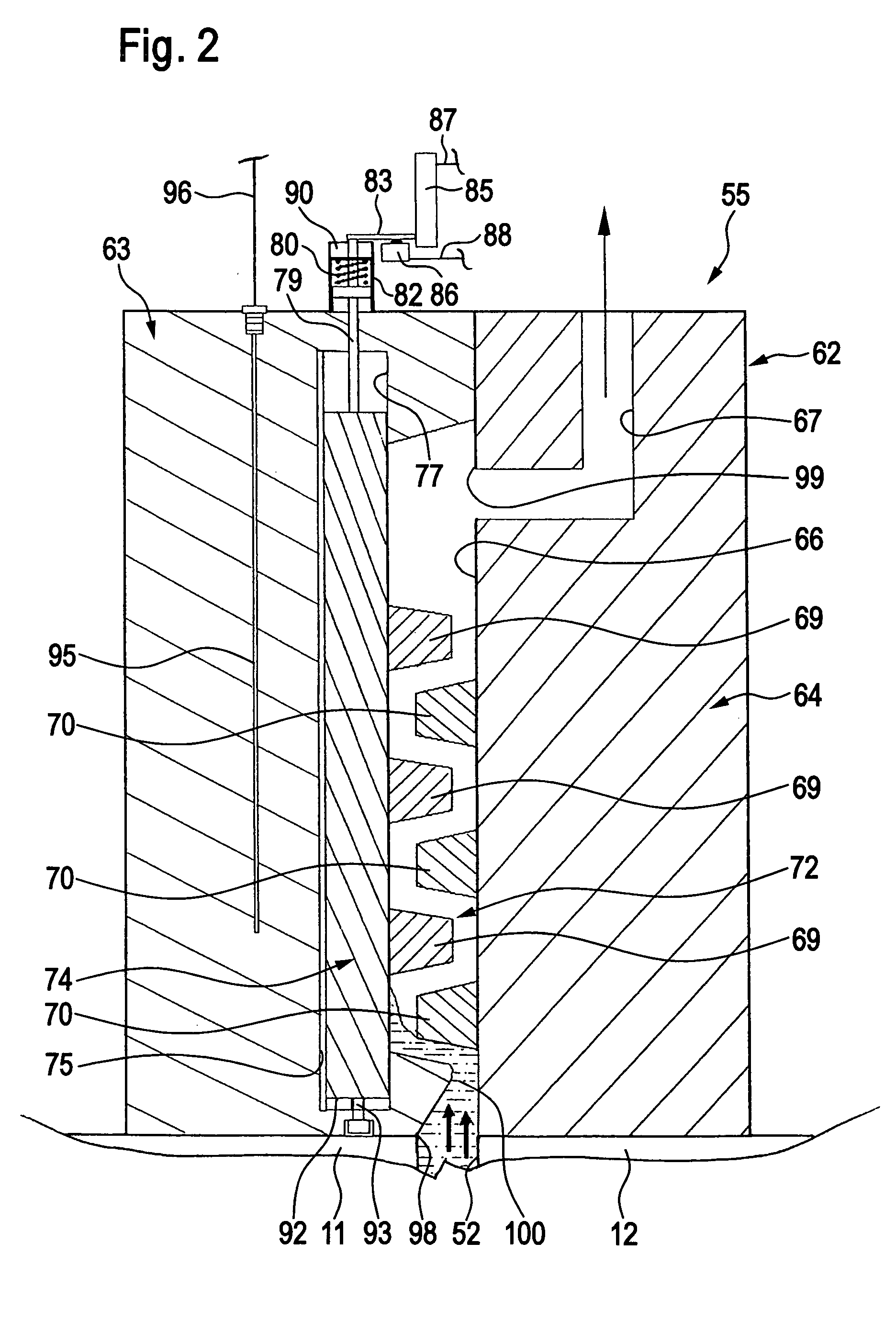
[0030]Schematically represented in FIG. 1 is a die casting device 10 according to the invention, which has a first, movable die half 11 and a second, fixed die half 12, which interact in the customary way with a die closing unit that is known per se, and therefore not represented in the drawing. Said closing unit comprises a movable platen and a fixed platen, which are not represented in the drawing to achieve a better overview and on each of which one of the two die halves 11, 12 is held in a known way. By means of the die closing unit, a predeterminable closing force can be exerted on the two die halves 11, 12. The two die halves 11, 12 form between them a mold cavity 14, which has the form of a casting to be cast and into which a casting material, for example a molten metal, preferably liquid aluminum or magnesium material, can be injected. For this purpose, the mold cavity 14 has an inlet opening, which is usually referred to as the “gate” and in FIG. 1 is provided with the desi...


PUM

PropertyMeasurementUnit
elastic restoring forceaaaaaaaaaa
timeaaaaaaaaaa
forceaaaaaaaaaa

Abstract

The invention relates to a venting unit for a die casting device which has a mold cavity that is adapted to be filled with liquid casting material and a gas suction device that is connected to the mold cavity for extracting gas from the mold cavity by suction, the venting unit comprising a flow labyrinth, the inlet of which is adapted to be connected to the mold cavity and the outlet of which is adapted to be connected to the gas suction device. In order to develop the venting unit in such a way that it makes improved evacuation of the mold cavity possible without the risk that liquid casting material can escape from the venting unit, it is proposed according to the invention that the flow cross-section of the flow labyrinth is variable. Furthermore, a die casting device with a venting unit of this kind is proposed.

Description

[0001]This application is a continuation of international application number PCT / EP2008 / 006180 filed on Jul. 26, 2008 and claims the benefit of German patent application no. 10 2007 054 520.9 filed on Nov. 6, 2007.[0002]The present disclosure relates to the subject matter disclosed in international application number PCT / EP2008 / 006180 of Jul. 26, 2008 and German application number 10 2007 054 520.9 of Nov. 6, 2007, which are incorporated herein by reference in their entirety and for all purposes.BACKGROUND OF THE INVENTION[0003]The invention relates to a venting unit for a die casting device which has a mold cavity that is adapted to be filled with liquid casting material and a gas suction device that is connected to the mold cavity for extracting gas from the mold cavity by suction, the venting unit comprising a flow labyrinth, the inlet of which is adapted to be connected to the mold cavity and the outlet of which is adapted to be connected to the gas suction device.[0004]The inve...

Claims


Application Information

Patent Timeline
Patent Type & Authority Applications(United States)
IPC IPC(8): B22C19/00B22C9/00
CPCB22D17/145B22C9/067
Inventor GAUERMANN, JOERG
Owner ELECTRONICS GMBH VERTRIEB ELEKTRONISCHER GERATE
Why Eureka
Try Eureka