Fuel pump assembly for a fuel pump module

a technology of fuel pump and fuel module, which is applied in the direction of piston pump, positive displacement liquid engine, separation process, etc., can solve the problems of limiting the efficiency of such assemblies, axially too high for current fuel pump modules to be packaged in such a location, and affecting the cooling and cleaning of the commutator, so as to reduce or eliminate the related hoses

Inactive Publication Date: 2008-12-04
TI GRP AUTOMOTIVE SYST LLC
View PDF43 Cites 14 Cited by
  • Summary
  • Abstract
  • Description
  • Claims
  • Application Information

AI Technical Summary

Benefits of technology

[0005]A fuel pump assembly according to one implementation includes a fuel pump, and an electric motor for rotatably driving the fuel pump, and including a motor armature, and a commutator positioned between the motor armature and the fuel pump. The commutator position may facilitate cooling and cleaning of the commutator. The fuel pump assembly may further include a fuel inlet and outlet disposed at a pump end of the assembly to reduce or eliminate related hoses, hose routing, and hose interconnections.

Problems solved by technology

Such assemblies experience a high viscous drag because the armature is spinning in a liquid such as gasoline or diesel fuel rather than air.
Such windage losses limit the efficiency of such assemblies.
But, current fuel pump modules are axially too tall to be packaged in such a location.

Method used


Image

  • Fuel pump assembly for a fuel pump module
  • Fuel pump assembly for a fuel pump module
  • Fuel pump assembly for a fuel pump module

Examples


Embodiment Construction

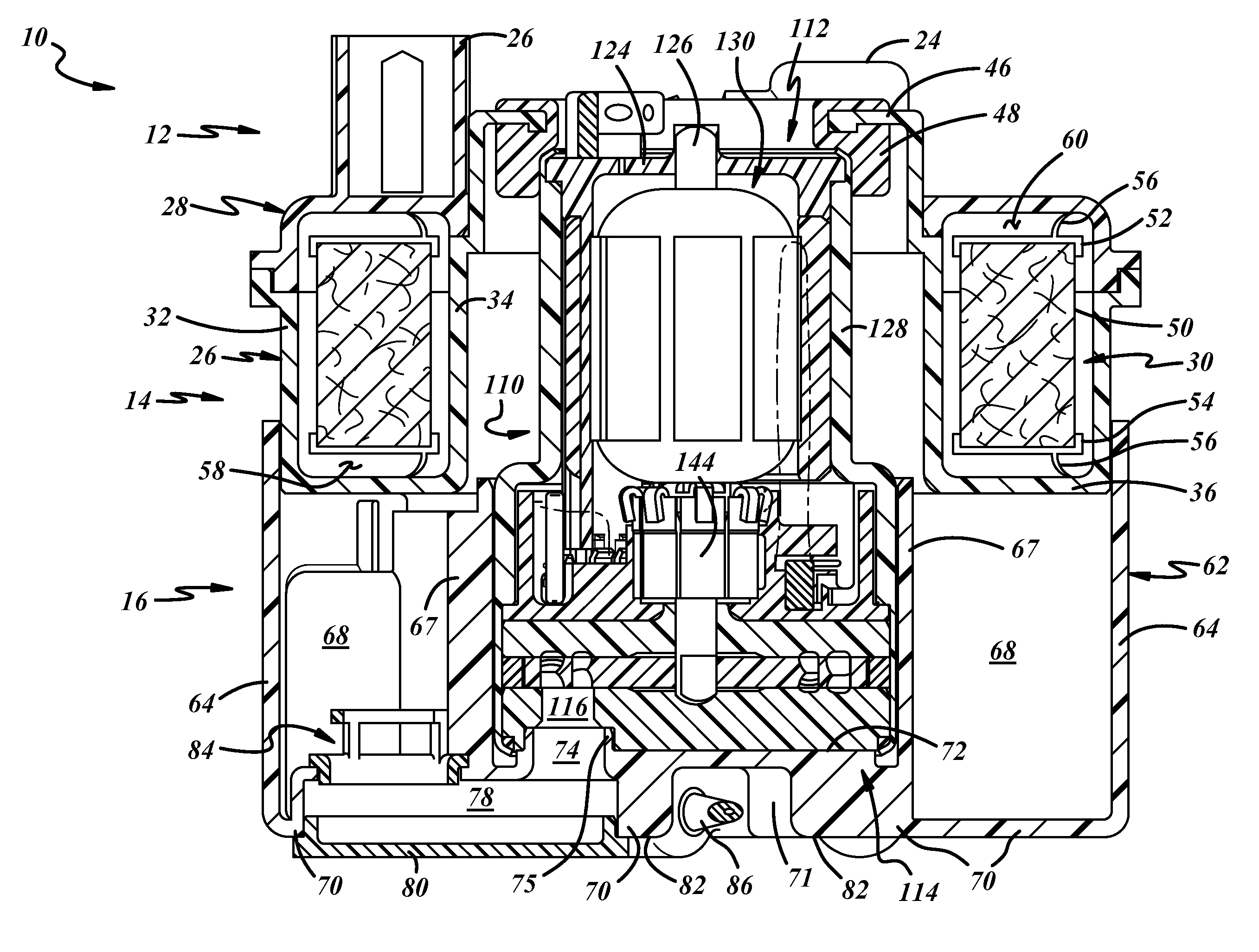
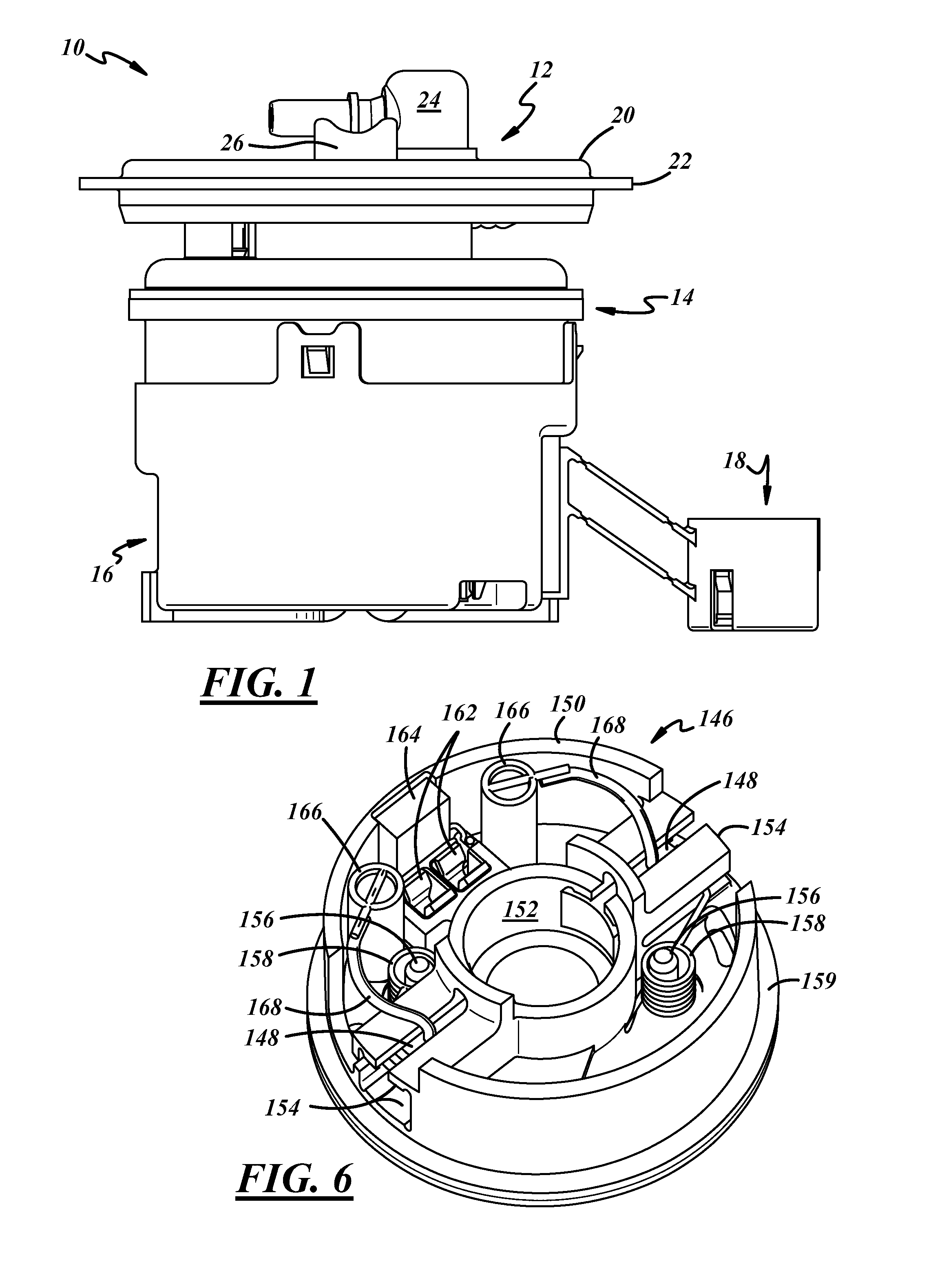
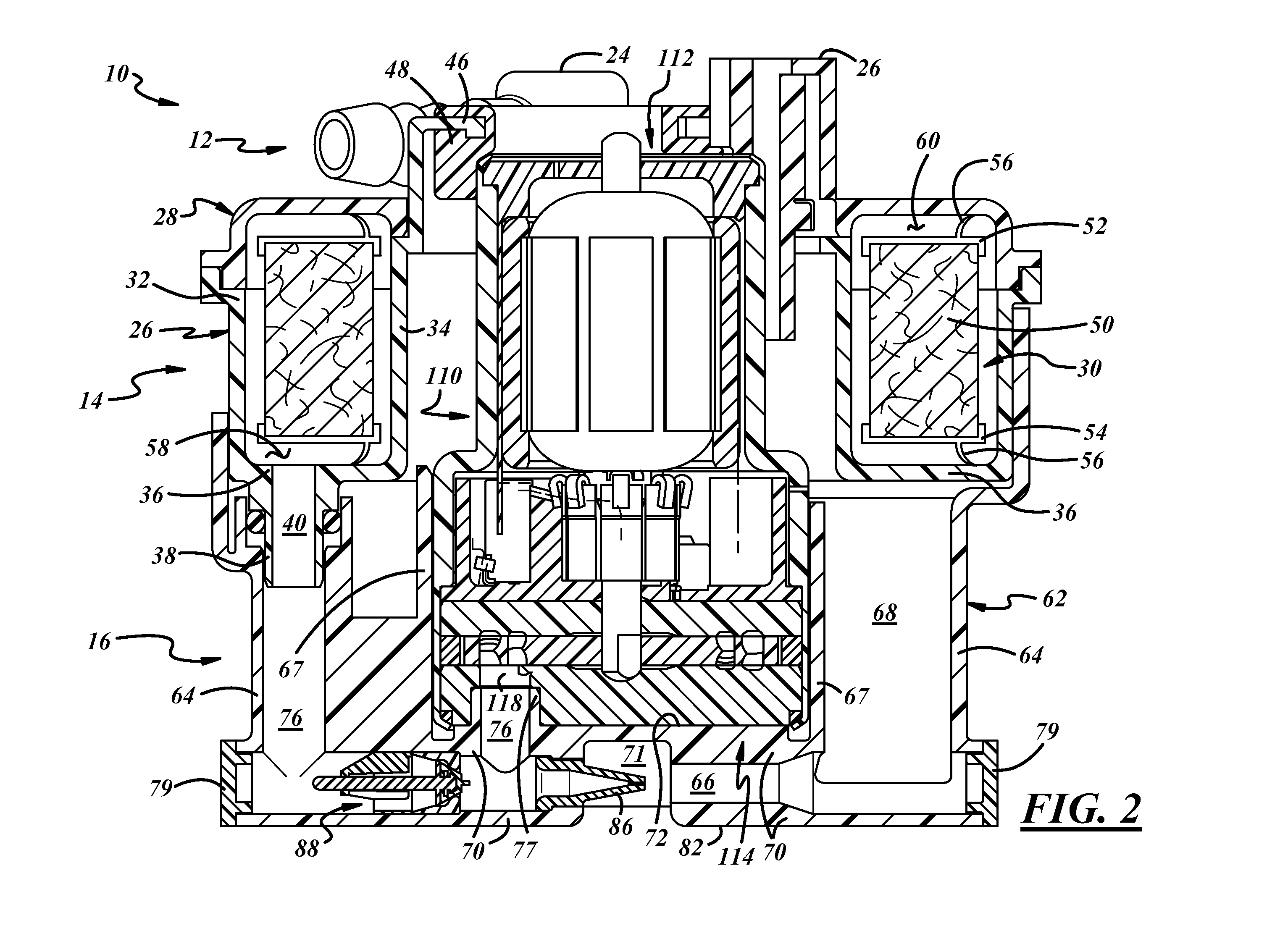
[0017]Referring in more detail to the drawings, FIG. 1 illustrates a presently preferred form of a fuel pump module 10 for drawing fuel from within a fuel tank (not shown) and pressurizing and filtering the fuel for delivery to an engine (not shown). In general, the fuel pump module 10 as shown in FIG. 1 may include a mounting flange 12 for mounting to the fuel tank within an aperture thereof, a filter assembly 14 carried by the mounting flange 12 for filtering fuel, a reservoir assembly 16 carried by the filter assembly for holding a quantity of fuel, and a piezo electric level sensor 18 for measurement of fuel level or fuel quantity in the fuel tank. Other types of level sensors such as resistor card level sensors could also be used. Referring to FIG. 2, the fuel pump module 10 may also include a fuel pump assembly 110 carried by the reservoir assembly 16 for drawing fuel from the reservoir assembly 16 and pressurizing the fuel for delivery to the filter assembly 14 and downstream...


PUM

PropertyMeasurementUnit
width-to-depth aspect ratioaaaaaaaaaa
diameteraaaaaaaaaa
diameteraaaaaaaaaa

Abstract

A fuel pump assembly includes a fuel pump, and an electric motor for rotatably driving the fuel pump and including a motor armature and a commutator positioned between the motor armature and the fuel pump.

Description

FIELD OF THE INVENTION[0001]The present invention relates generally to fuel pump modules for placement in fuel tanks and more particularly to fuel pump assemblies.BACKGROUND OF THE INVENTION[0002]In-tank fuel pump modules are used in automotive fuel delivery systems to draw fuel from a fuel tank and supply the fuel under pressure for delivery to an engine. These modules usually include a mounting flange closing an opening in an upper wall of the tank, a fuel reservoir carried by the mounting flange and disposed within the fuel tank, a fuel pump assembly disposed in the reservoir, and several hoses and hose interconnections between and among the mounting flange, fuel reservoir, and fuel pump assembly.[0003]In conventional electric motor driven fuel pump assemblies, a pump discharges fuel through a motor housing to cool the motor as the fuel flows past the motor and out of the pump outlet. Such assemblies experience a high viscous drag because the armature is spinning in a liquid such...

Claims


Application Information

Patent Timeline
Patent Type & Authority Applications(United States)
IPC IPC(8): F04B17/03F02M37/44F02M37/46F02M37/48F02M37/50
CPCF02M37/08F02M37/10F02M37/22F04D5/002H02K5/148H02K7/14H02K23/04F02M37/50F02M37/46F02M37/44F02M37/48
Inventor GETTEL, BRYAN J.KUPERUS, PETER P.
Owner TI GRP AUTOMOTIVE SYST LLC
Why Eureka
Try Eureka