[0006]The accumulator-type injection
system according to the invention for injecting fuel from an accumulator into a
combustion chamber of an internal combustion engine has the
advantage that leaks at the accumulator-type injection system do not lead to
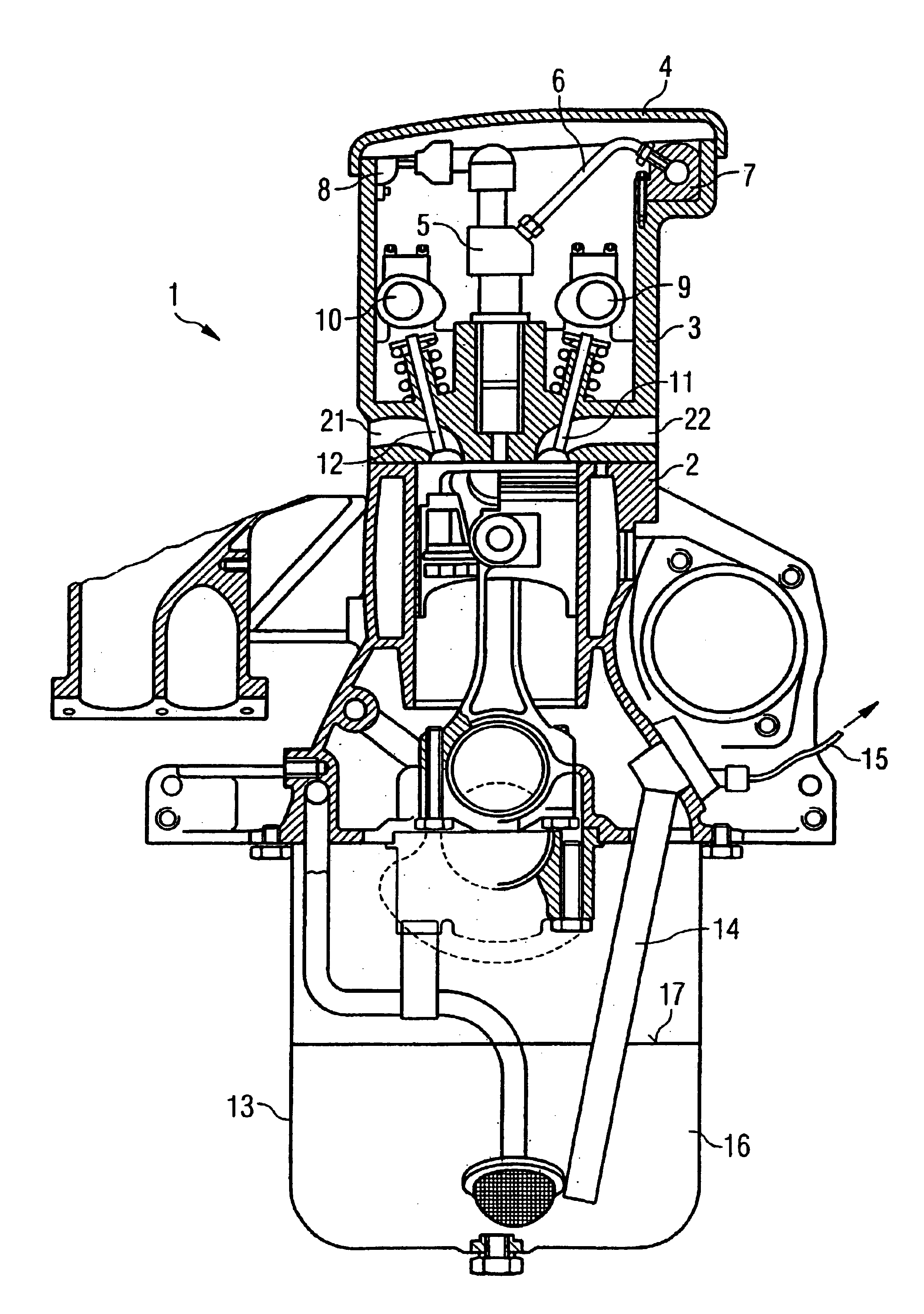
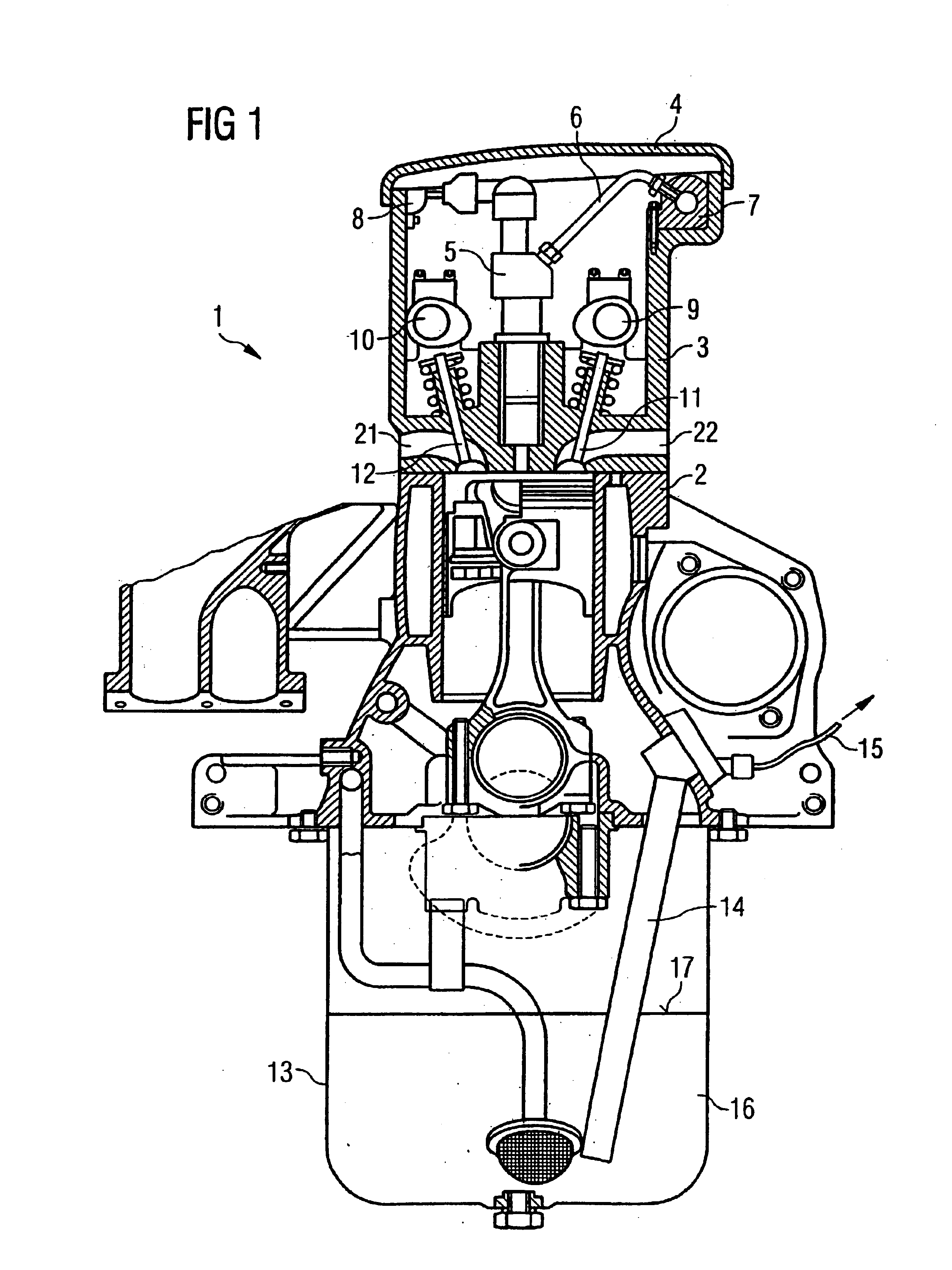
pollution of the environment and no leakage escapes to the outside. This is achieved according to the invention in that the injectors are arranged completely within a cylinder head of the internal combustion engine. As a result, a leak at the
injector or a feedline to the injector does not escape to the outside but rather remains in the interior of the cylinder head of the internal combustion engine in which, for example, one or more camshafts for
charge cycle valves may be arranged. As the injector is arranged completely in the cylinder head, the injector is also encapsulated in the cylinder head so that a significant reduction in the injector
noise is achieved. Furthermore, an improved engine design can be achieved as a particularly compact design of the internal combustion engine without the previously outwardly protruding injectors can be achieved.
[0007]According to one preferred embodiment of the present invention, the accumulator is furthermore also arranged within the cylinder head of the internal combustion engine. As a result, even greater protection against the escaping of fuel into the environment is achieved as a large number of the components of the accumulator-type injection system are arranged within the cylinder head. Furthermore, this permits a design with particularly short routing of the lines, which provides corresponding hydraulic advantages, in particular lower flow losses.
[0008]According to a further preferred embodiment of the present invention, the accumulator of the accumulator-type injection system is arranged directly on or at the cylinder head of the internal combustion engine. This arrangement also permits particularly short routing of the lines to be achieved, but in comparison with an arrangement of the accumulator in the cylinder head there is a somewhat greater risk of fuel escaping into the environment when there are leaks at the accumulator.
[0009]In order to avoid disadvantages in terms of degraded
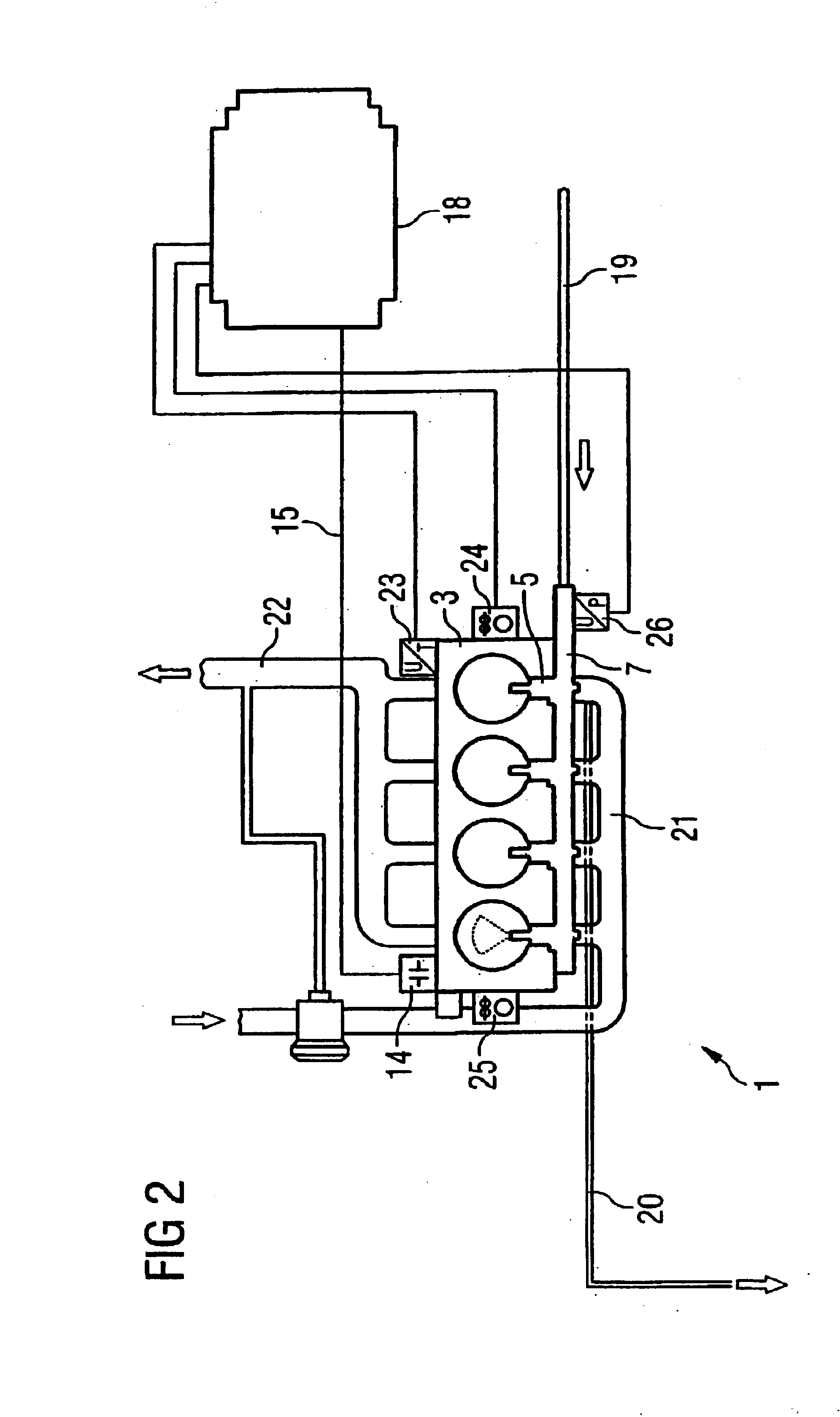
oil quality, when there is a leak in the accumulator-type injection system with the injectors or feedlines to the injectors or the rail arranged in the cylinder head of the internal combustion engine, an oil sensor which senses the quality of the engine oil is preferably provided. In fact, when there is a leak of fuel with an arrangement of one or more components of the accumulator-type injection system in the cylinder head, the fuel in the interior of the cylinder head escapes and thus contaminates the engine oil with fuel. As a result the engine oil is diluted by the fuel. The provision of an oil sensor to determine the quality of the engine oil thus makes it possible to determine a leak in the accumulator-type injection system by determining the
dilution of the engine oil with fuel. As a result, serious damage to the internal combustion engine owing to diluted engine
oil can be prevented.
[0010]Furthermore, an oil sensor, which senses the filling level of the engine oil, is preferably provided. As the filling level would rise when fuel leaks into the engine oil, redundant determination of a leak at the accumulator-type injection system can thus be made possible, for example. Of course, the oil sensor for the filling level can also be used in a customary way to determine the absence of engine oil. The oil sensor is particularly preferably constructed in such a way that it can simultaneously sense the quality of the engine oil and the filling level of the engine oil. As a result, only one oil sensor is necessary, permitting the design to be minimized in terms of equipment.
[0013]The leakage line or the fuel return flow line is preferably arranged within the cylinder head, providing a particularly compact design.

