Device for separating foreign particles out of the cooling air that can be fed to the rotor blades of a turbine

a technology of cooling air and foreign particles, which is applied in the direction of machines/engines, mechanical equipment, liquid fuel engines, etc., can solve the problems of radially inward directed cooling air stream entanglement of lightweight and smaller dust or foreign particles for further cooling of the turbine rotor blade, and the risk of contamination, so as to improve the separation effect and boost the effect of separation

Inactive Publication Date: 2005-01-06
ALSTOM TECH LTD
View PDF4 Cites 15 Cited by
  • Summary
  • Abstract
  • Description
  • Claims
  • Application Information

AI Technical Summary

Benefits of technology

[0019] A second proposed solution for improving the separation of foreign particles out of the cooling air that can be fed to the rotor blades of a turbine provides a concrete improvement to the device described in EP 1 174 589 A1 for removing foreign particles or dust particles from the cooling air of a gas turbine. Unlike in the case outlined above, the diverter unit, together with wall parts of the turbine stator unit, encloses a type of annular chamber in the sense of a separating chamber, in which the dust or foreign particles are separated out of the cooling air that is fed to the turbine rotor blade for cooling purposes. In this case, the cooling air originating from a compressor unit flows via a nozzle unit into the annular chamber; according to the invention, the nozzle units each provide a nozzle duct having a duct longitudinal axis that determines the direction of flow of the cooling-air stream and is inclined radially in such a manner that the cooling-air stream passing through the nozzle duct is directed radially outward. The annular chamber is connected, via at least two through-openings, to the annular space, which is delimited by wall parts of the turbine stator and the rotating wheel disk. One of the at least two through-openings is located on the radially outer side, between the diverter unit and the turbine stator unit, and the other is arranged on the radially inner side, with the duct longitudinal axis of the nozzle unit being arranged aligned with the radially outer through-opening. The cooling air mixed with foreign particles therefore flows through the annular chamber through the radially outer through-opening, virtually without obstacle, and then passes over corresponding flow contours provided at the rotating wheel disk and the turbine stator unit without obstacle into the working duct of the gas turbine. Therefore, on account of the radially outwardly directed cooling-air stream, there is fundamentally no need for centrifugal forces acting on the individual foreign particles, as is the case in the prior art cited above, to produce a desired separation effect. Although in the case according to the invention the cooling air flowing into the annular chamber in the circumferential direction also causes centrifugal forces to act on the foreign particles, thereby advantageously boosting the separation effect, the separation effect is not based exclusively on the centrifugal effect, thereby ensuring that even foreign particles of relatively low mass can be extracted from the cooling air that is actually to be fed to the rotating wheel disk.

Problems solved by technology

Deposits of this nature on the surface of the radially inner, shorter L limb lead to a risk of contamination to the cooling-air stream that forms in the annular space which should not be underestimated yet to which it is quite obvious that no further attention is paid in the above-mentioned document.
Although it is possible to separate out relatively high-mass foreign particles using the separation method described in this document, it is impossible to rule out lightweight and smaller dust or foreign particles being entrained by the radially inwardly directed cooling-air stream for further cooling of the turbine rotor blade.

Method used


Image

  • Device for separating foreign particles out of the cooling air that can be fed to the rotor blades of a turbine
  • Device for separating foreign particles out of the cooling air that can be fed to the rotor blades of a turbine
  • Device for separating foreign particles out of the cooling air that can be fed to the rotor blades of a turbine

Examples


Embodiment Construction

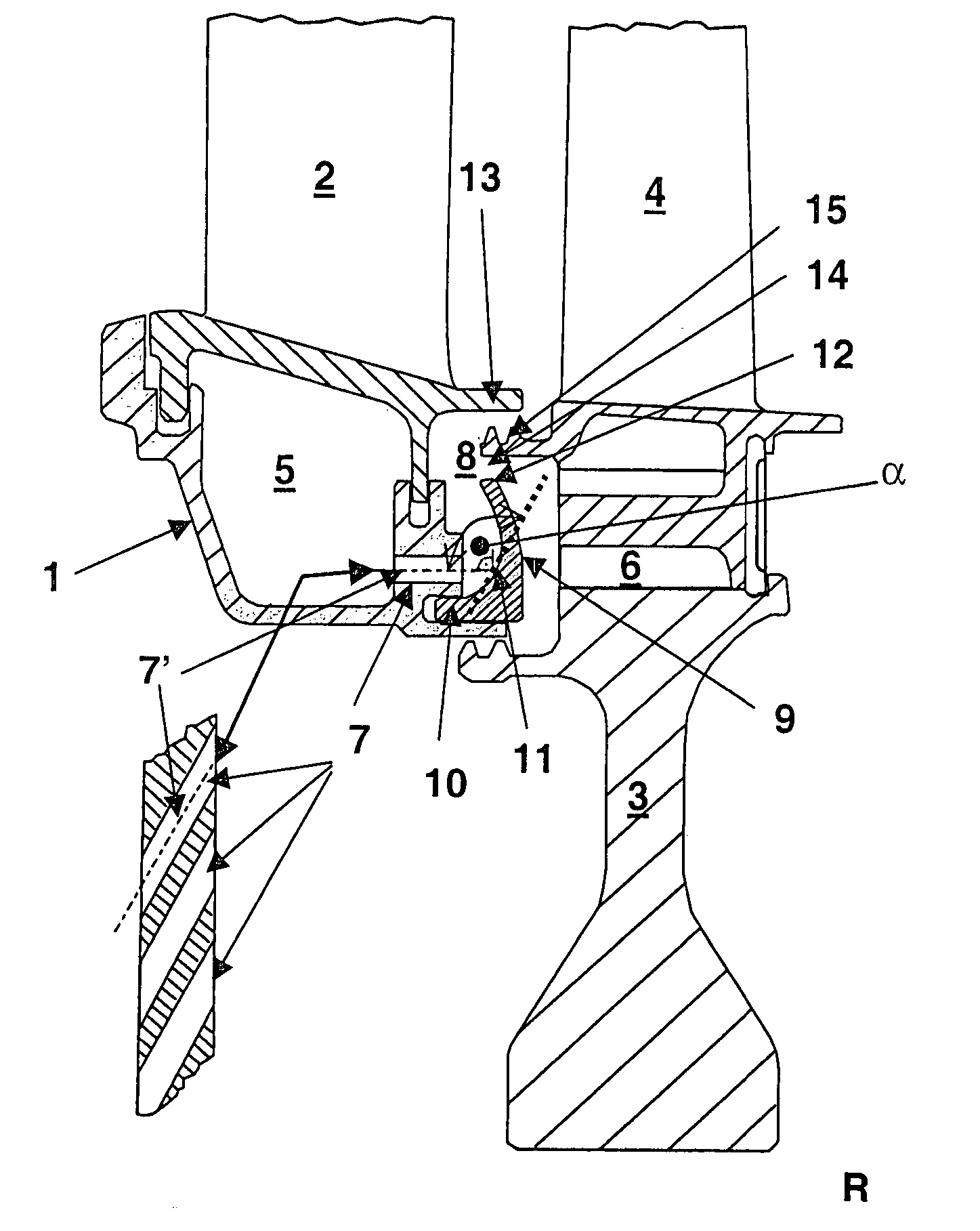
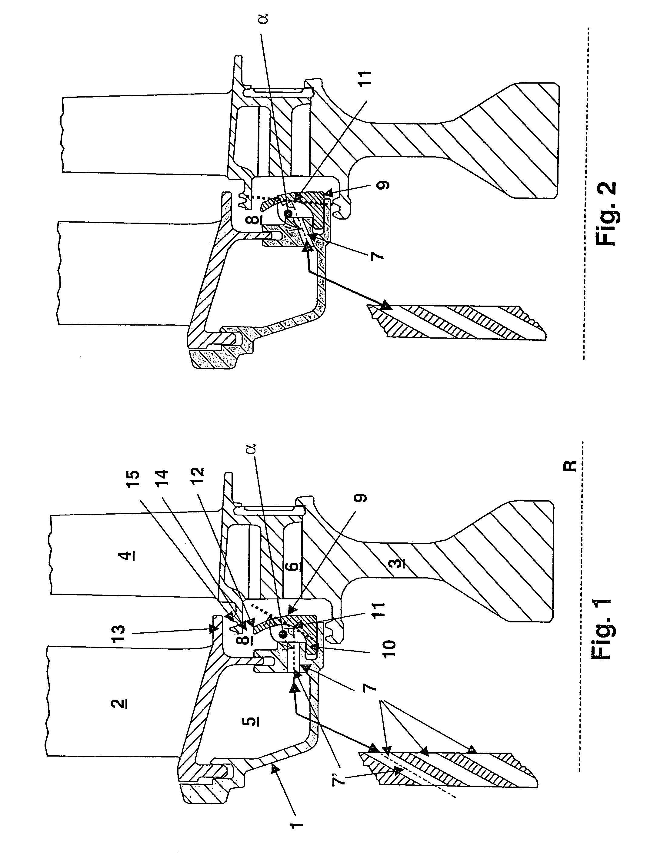
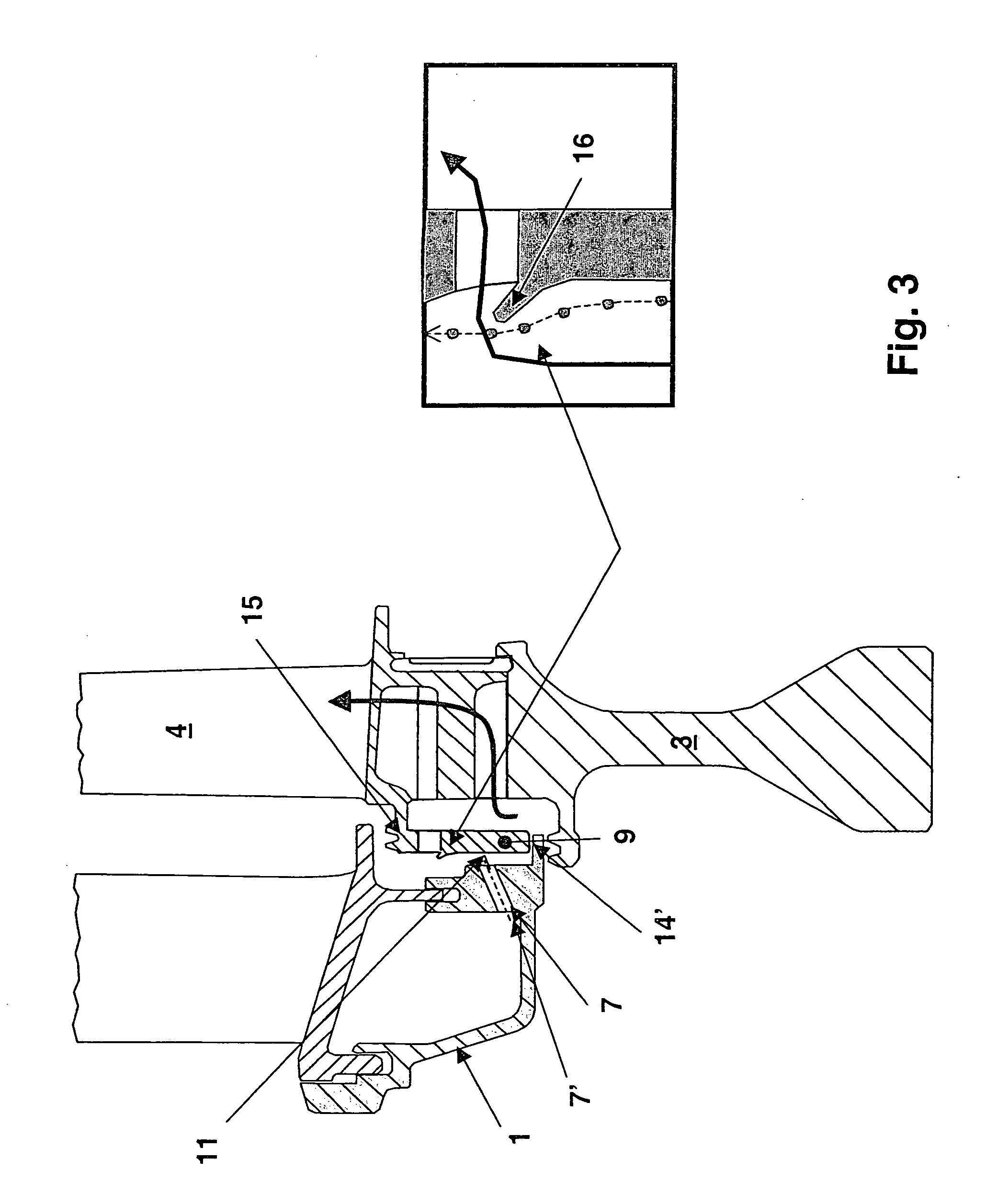
[0029]FIG. 1 shows a longitudinal section through a turbine stator 1 having a guide vane 2 that is fixedly connected thereto and a wheel disk 3, which is arranged such that it can rotate about the rotor axis R and has a turbine rotor blade 4 secured to it. Cooling air which is mixed with foreign particles, for example dust particles, passes from a compression unit (not shown) into a volume 5 enclosed between guide vane 2 and turbine stator 1. Specifically, the cooling air supplied by the compression unit is to be separated from the foreign particles, and the cleaned cooling air is to be passed, for further cooling of the rotor blade 4, into the cooling ducts 6 provided accordingly for this purpose within the wheel disk 3, which are connected to a hollow-chamber system provided accordingly for cooling purposes within the rotor blade 4.

[0030] To separate the foreign particles out of the cooling air fed by the compression unit, the cooling air passes out of the volume 5, via nozzle un...


PUM


Abstract

A device separates foreign particles from cooling air fed to turbine rotor blades. The cooling air is fed directly or indirectly via stationary nozzle units to an annular space between wall parts of a turbine stator and rotating wheel disk as a cooling-air stream in the circumferential direction. The annular space communicates with ducts, arranged in the disk, for feeding the cooling air into the blades. A diverter unit is provided inside the annular space or so as to delimit the annular space on one side, so cooling air emerging from the nozzle units, before entering the ducts, is diverted on one side and foreign particles are centrifugally thrown into a radially outer part of the annular space and separated therefrom with a barrier-air fraction. The diverter unit has a surface region on which the stream impinges so it can be diverted radially outward through an angle greater than 90°.

Description

CROSS-REFERENCE TO RELATED APPLICATIONS [0001] This application claims priority to German application No. 103 30 471.1 filed on Jul. 5, 2003, the entire content of which is expressly incorporated herein by reference thereto. FIELD OF THE INVENTION [0002] The invention relates to a device for separating foreign particles out of the cooling air that can be fed to the rotor blades of a turbine, in particular for a gas turbine arrangement. The cooling air can be fed directly or indirectly via stationary nozzle units to an annular space that is formed between wall parts of a turbine stator and a rotating wheel disk, as a cooling-air stream is directed in the circumferential direction. The annular space is in communication with ducts, arranged in the wheel disk, for feeding the cooling air into the rotor blades. A diverter unit is provided inside the annular space or so as to delimit the annular space on one side. By means of the diverter device, the cooling air that emerges from the nozz...

Claims


Application Information

Patent Timeline
Patent Type & Authority Applications(United States)
IPC IPC(8): F01D25/32
CPCF01D5/082F05D2260/607F01D11/001
Inventor FRIED, REINHARDWEIGAND, BERNHARD
Owner ALSTOM TECH LTD
Why Eureka
Try Eureka