Bipolar plate for a fuel cell
a fuel cell and bipolar plate technology, applied in the direction of fuel cells, fuel cell details, cell components, etc., can solve the problems of affecting the entire fuel cell system, and achieve the effect of reducing pressure losses and improving uniform distribution of operating medium
- Summary
- Abstract
- Description
- Claims
- Application Information
AI Technical Summary
Benefits of technology
Problems solved by technology
Method used
Image
Examples
first example
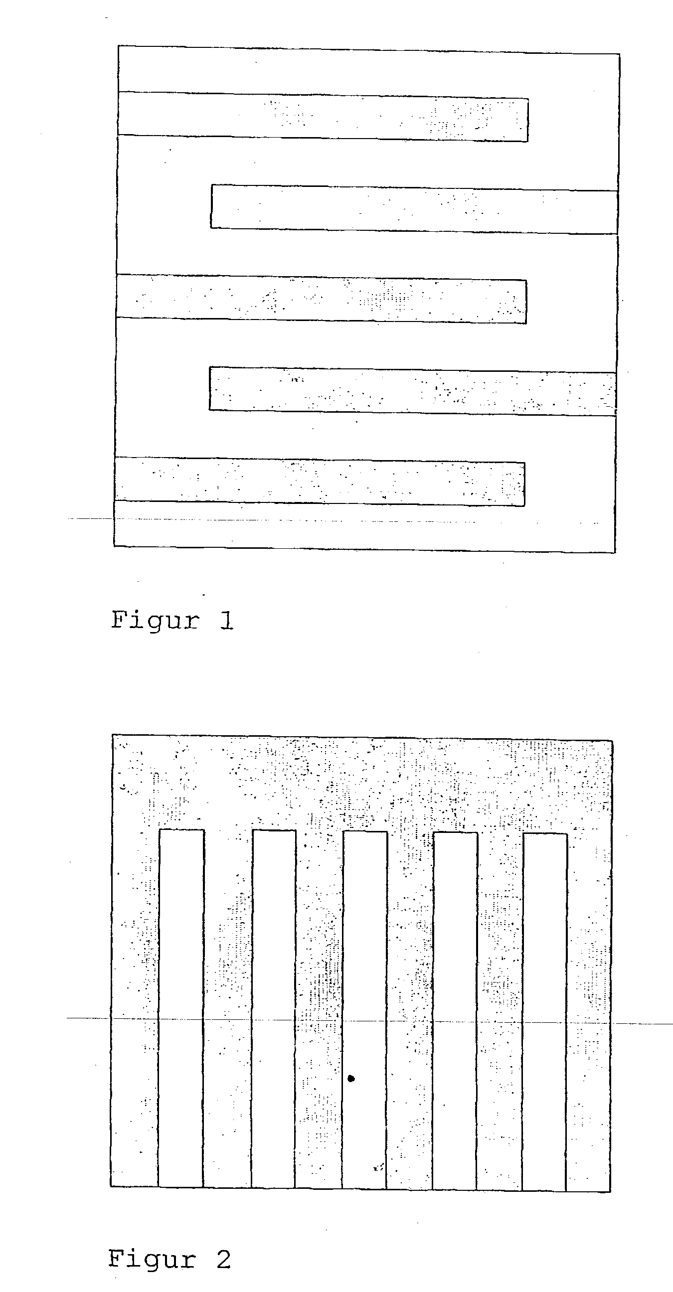
[0021] In a direct methanol fuel cell CO.sub.2 is produced in the cavity compartment and becomes available as a gas. To discharge these CO.sub.2 gas bubbles and to avoid flow losses, the anode compartment has to have a minimum dimension as the compartment height. With conventional gas distributor structures of a bipolar plate, the operating medium is directly fed to the electrode surfaces. The contact surfaces between the bipolar plate and the electrode surfaces (ribs) hardly contribute to conversion. With the bipolar plate according to the invention with porous structures in the regions of the ribs, the distribution of the drive medium is also effected below the ribs. The conversion can thus be increased and / or a more compact construction can be possible. Simultaneously, a more effective removal of the CO.sub.2 bubbles is ensured.
second example
[0022] With the previously described direct methanol fuel cell and polymer electrolyte membrane fuel cells, the problem arises that water is produced at the cavity side and water from the anode side passes through the membrane by electroosmosis or emerges from the electrolyte. This water plugs up as a rule, the channels on the cathode side so that transport limitations arise with respect to oxygen. The output and efficiency of the fuel cells are negatively influenced in a detrimental manner. With the distributor structure according to the invention of the bipolar plate, the cavity exhaust gas collecting channel can be eliminated and the water discharged over the entire surfaces to ensure an effective removal of the water. The embodiment according to FIG. 2 provides the possibility that the gas, in the case of plugged-up channels will be discharged through the hydrophobic porous region.
PUM
 Abstract
Description
Claims
Application Information
 - R&D
- Intellectual Property
- Life Sciences
- Materials
- Tech Scout
- Unparalleled Data Quality
- Higher Quality Content
- 60% Fewer Hallucinations
Browse by: Latest US Patents, China's latest patents, Technical Efficacy Thesaurus, Application Domain, Technology Topic, Popular Technical Reports.
© 2025 PatSnap. All rights reserved.Legal|Privacy policy|Modern Slavery Act Transparency Statement|Sitemap|About US| Contact US: help@patsnap.com


