
Multi-disk clutch or multi-disk brake with axial oil flow

Inactive Publication Date: 2008-01-10
ZF FRIEDRICHSHAFEN AG
View PDF13 Cites 9 Cited by
  • Summary
  • Abstract
  • Description
  • Claims
  • Application Information

AI Technical Summary

Benefits of technology

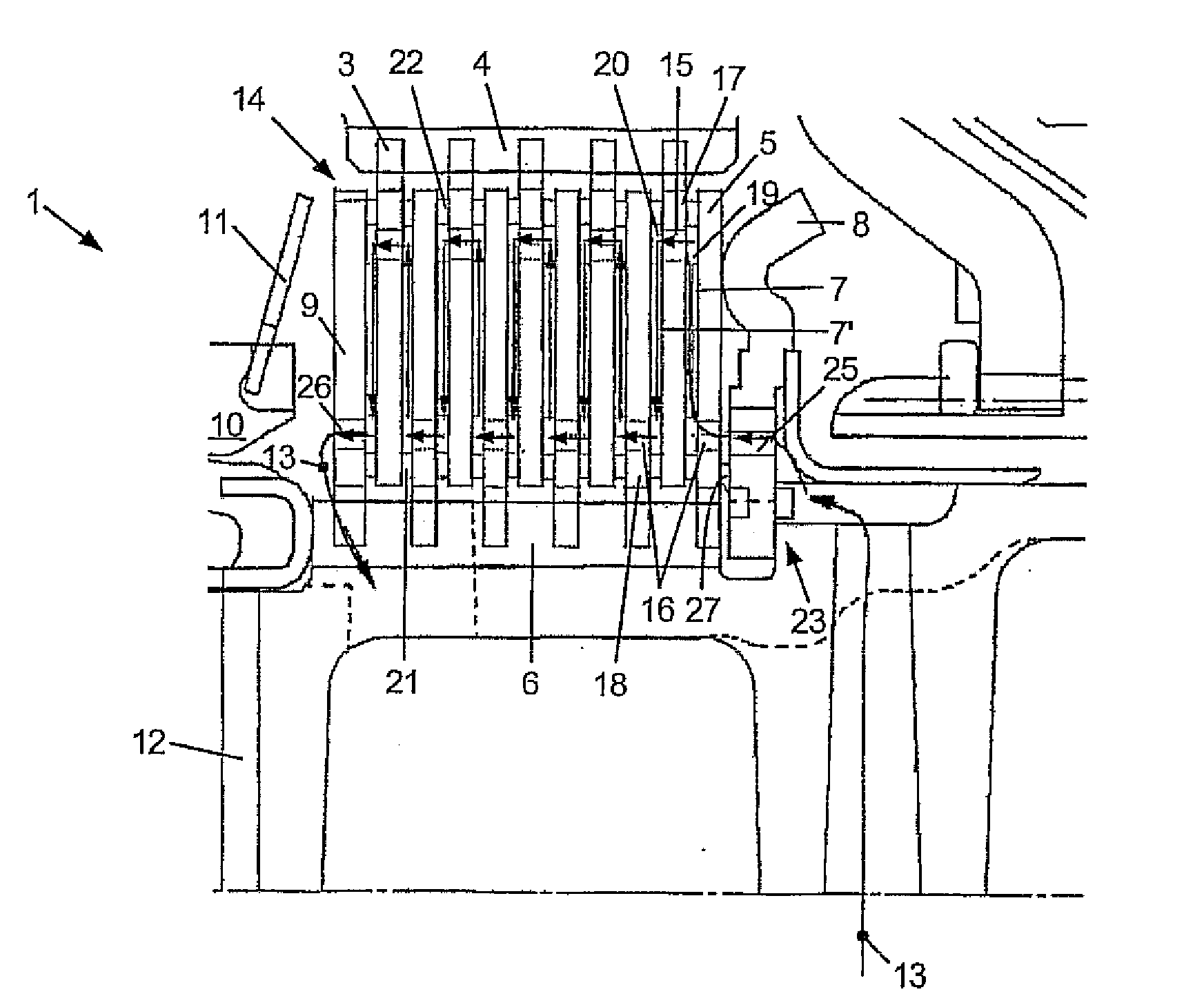
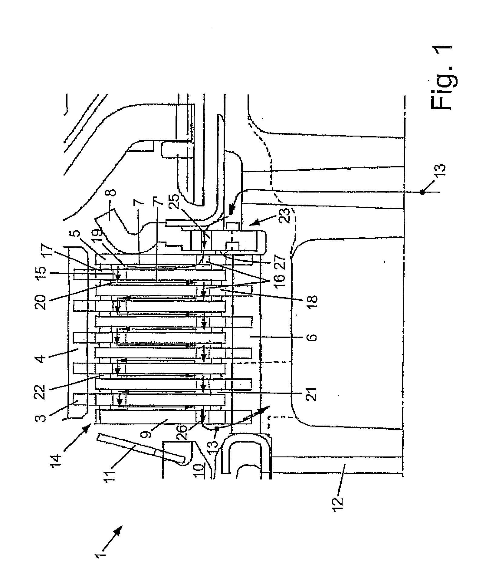
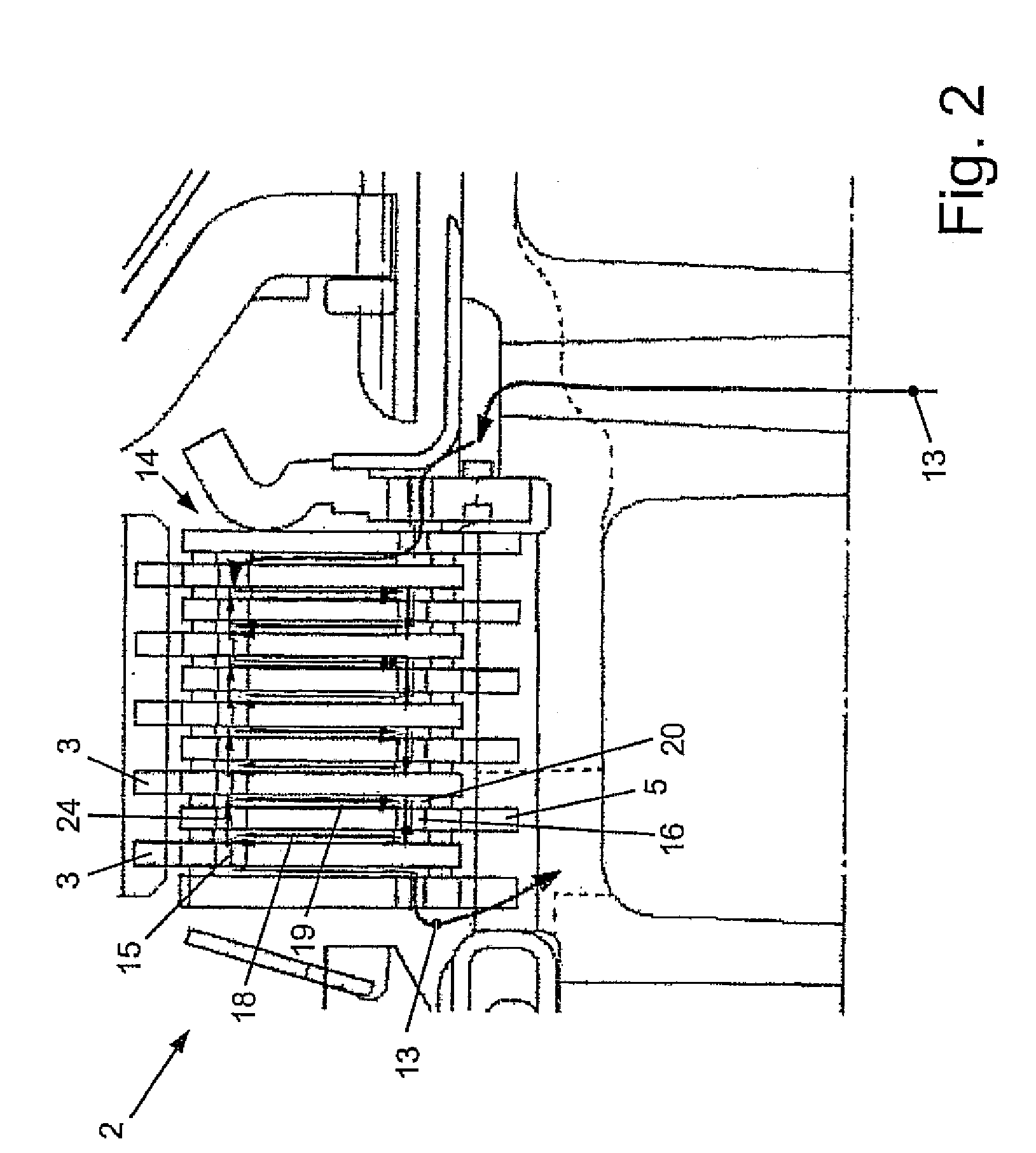
[0009]The invention is based on the realization that the evacuation of heat, from a multi-disk clutch or multi-disk brake, can be improved if the cooling oil is pumped in a predefined manner through the same such that, on the one hand, the cooling oil volume coming in contact with the disk surfaces to be cooled per unit of time is increased and, on the other hand, the cooling oil can reach the friction linings of the disk to be cooled better than before.
[0023]Finally, it may be provided that the cooling oil is pumped into an annular oil collecting chamber, which is configured adjacent to the end disk on the inflow side in the region of the multi-disk clutch or multi-disk brake, before passing through the clutch pack. In this way, particularly the distribution of the cooling oil is facilitated.

Problems solved by technology

In the case of a wet-running multi-disk brake which is used, for example, as a shifting member in an automatic multi-ratio transmission, this radial conveyance of the cooling oil is not possible or is possible only with great difficulty because, during the engagement of the brake, a rotating brake component is brought to a halt against a stationary brake component while absorbing energy.

Method used


Image

  • Multi-disk clutch or multi-disk brake with axial oil flow
  • Multi-disk clutch or multi-disk brake with axial oil flow
  • Multi-disk clutch or multi-disk brake with axial oil flow

Examples


Embodiment Construction

[0027]FIG. 1 accordingly shows a multi-disk brake 1, according to a first embodiment of the invention. This multi-disk brake 1 is configured, by way of example, as a shifting member of an automatic transmission and comprises, first of all, an inner disk carrier 4 carrying an internal disk with the carrier being connected to a rotatable component of the automatic transmission, the component not being illustrated here. Furthermore, the multi-disk brake 1 has an outer disk carrier 6 carrying an external disk 5, the carrier being non-rotatably connected to the housing 12 of the automatic transmission. The internal disks 3 and the external disks 5 are alternately disposed axially adjacent to each other and, together with two end disks 8 and 9, form a clutch pack 14. A piston 10 of a pressurant-actuated piston-cylinder arrangement can apply an axially actuating force, that engages the multi-disk brake 1, on one end disk 9 while the opposite end disk 8 is firmly connected to the housing 12...


PUM


Abstract

The invention relates to a multi-disk clutch or multi-disk brake (1, 2), comprising an inner disk carrier (4) carrying internal disks (3) and an outer disk carrier (6) carrying external disks (5), friction linings (7, 7′) on the internal and external disks (3, 5), a first end disk (9), on which a closing force for the multi-disk clutch or multi-disk brake can be applied by a piston (10) of a piston-cylinder arrangement which can be actuated by a pressure medium, and a second end disk (8), which forms an axial abutment for the clutch pack (14) formed by the disks (3, 5, 8, 9), wherein the multi-disk clutch or multi-disk brake (1, 2) and / or the components encompassing the clutch or the brake are configured such that the internal and external disks (3, 5) can be wetted with a cooling oil (13). So as to improve heat dissipation during operation, it is provided that the multi-disk clutch or multi-disk brake (1, 2) is configured such that the cooling oil (13) can be directed axially through the clutch pack (14).

Description

[0001]This application claims priority from German Application Serial No. 10 2006 031 785.8 filed Jul. 10, 2006.FIELD OF THE INVENTION[0002]The invention relates to a multi-disk clutch or multi-disk brake comprising an inner disk carrier carrying internal disks and an outer disk carrying external disks, friction linings on the internal and external disks, a first end disk, on which an engaging force for the multi-disk clutch or multi-disk brake can be applied by a piston of a piston-cylinder arrangement which can be actuated by pressure medium, and a second end disk, which forms an axial abutment for the clutch pack formed by the disks, and wherein the multi-disk clutch or multi-disk brake and / or the components encompassing the clutch or the brake are configured such that the internal and the external disks can be wetted with a cooling oil.BACKGROUND OF THE INVENTION[0003]Multi-disk clutches or multi-disk brakes of this type are known in various embodiments. For example, they are us...

Claims


Application Information

Patent Timeline
IPC IPC(8): F16D13/72
CPCF16D13/72F16D25/123F16D25/0638
Inventor HAUPT, JOSEFSCHMIDT, THILOSCHIELE, PETERMILLER, TOBIASSCHWEMER, CHRISTIAN
Owner ZF FRIEDRICHSHAFEN AG
Learn More