Liquid filter

a liquid filter and filter body technology, applied in the direction of sedimentation settling tanks, lubricant mounting/connection, separation processes, etc., can solve the problems of contaminated threaded mounting flanges and any units, unable to remove residual fluid, and unable to collect excess oil, etc., to achieve the effect of easy insertion

Active Publication Date: 2009-09-08
MANN HUMMEL GMBH
View PDF24 Cites 13 Cited by
  • Summary
  • Abstract
  • Description
  • Claims
  • Application Information

AI Technical Summary

Benefits of technology

[0006]Another object is to provide a liquid filter with a replaceable filter element which stands upright, is easy to empty, inexpensive to construct and is just as reliable and simple to operate.
[0027]It is advantageous to provide an inspection window in the liquid filter in the lower area of the replaceable filter, preferably in the carrier module, such that it is possible to obtain information regarding the liquid level in the replaceable filter by looking through the inspection window. It is thus possible to easily determine whether the replaceable filter and a portion of the carrier module are completely emptied and thus whether the replaceable filter can be unscrewed and exchanged without any loss of liquid. This is the simplest way of making a reliable evaluation of the fluid level in the liquid filter. This inspection window may be made of glass or of a transparent plastic. The interior side of the window which faces the liquid is preferably treated by a type of lotus effect so that dirt particles and residual liquid do not adhere to the inspection window.

Problems solved by technology

When a liquid filter element is changed, there is often the problem of residential fluid leading into the environment when screwing open the cover or when exchanging the replaceable filter.
One disadvantage here is that despite the fact that the quantity of oil is reduced, the oil volume that is still present and runs out must be collected in some fashion for environmental reasons.
In addition, the escaping oil causes heavy contamination of the threaded mounting flange and any units that might be situated beneath it.

Method used


Image

  • Liquid filter
  • Liquid filter
  • Liquid filter

Examples


Embodiment Construction

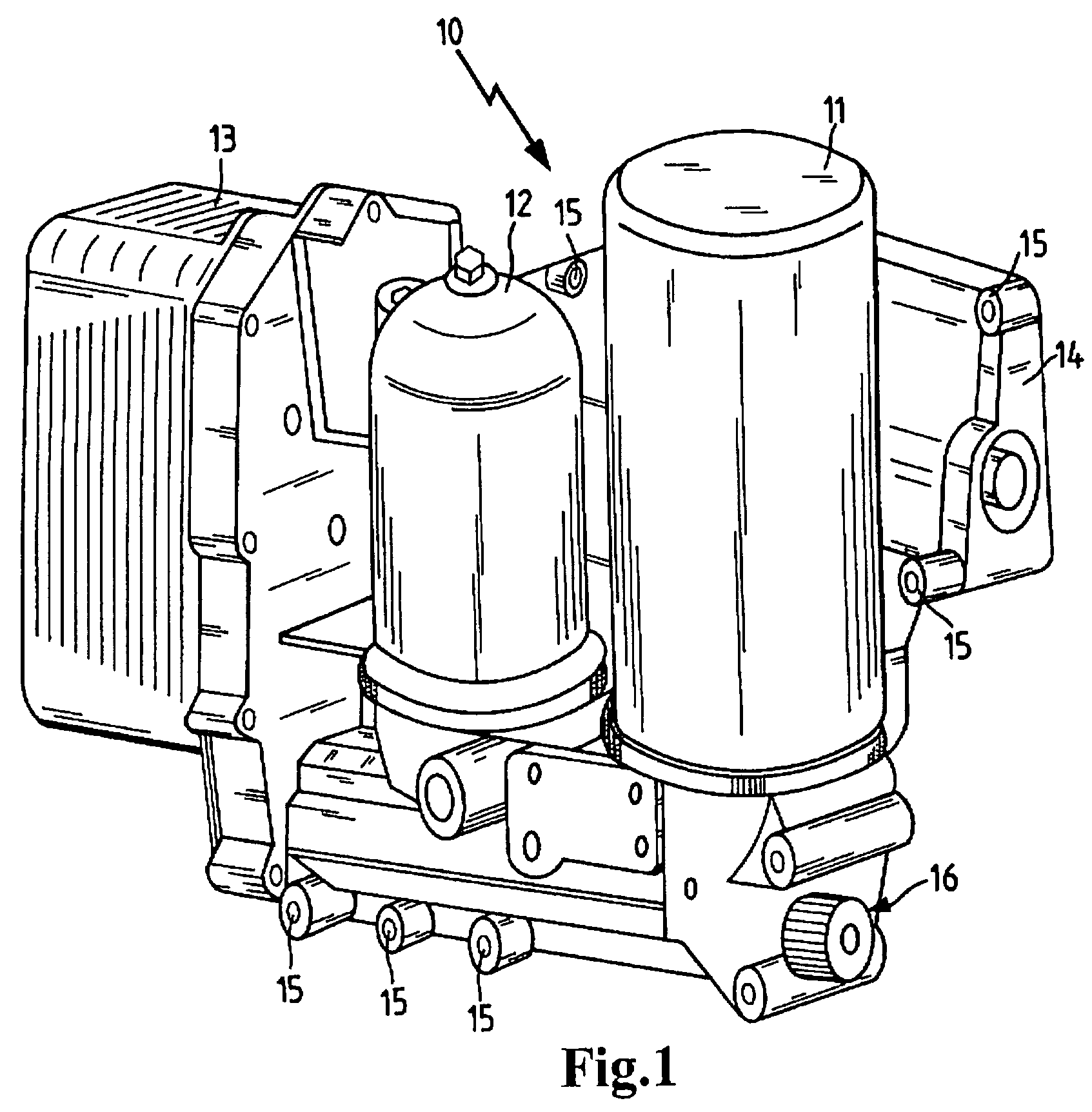
[0036]FIG. 1 shows a liquid filter 10 for lubricating oil in an internal combustion engine provided with a replaceable filter 11, a centrifuge 12 and an oil cooler 13, which are arranged on a carrier module 14. Channels (not shown here) are provided in the interior of the carrier module 14 for connecting the individual functional elements 11, 12, 13, but it is sufficient according to the invention to provide only a carrier module 14 with a single replaceable filter 11. The centrifuge 12 is preferably mounted a the bypass of the oil circulation system, and the unfiltered oil stream preferably is cooled down in the oil cooler 13 and then sent directly to the replaceable oil filter 11 for filtering.

[0037]Mounting bores 15, with which the carrier module together with the functional elements arranged on it can be flange-connected directly in the engine compartment or to the engine block of the internal combustion engine, are provided on the carrier module 14. The connection with the oil ...


PUM

PropertyMeasurementUnit
areaaaaaaaaaaa
pressureaaaaaaaaaa
axial displacementaaaaaaaaaa

Abstract

A liquid filter, particularly for the lubricating oil of an internal combustion engine, having at least one replaceable filter and a carrier module, in which the replaceable filter has a housing with an inlet and an outlet for the liquid to be filtered; a housing vessel with an opening pointing essentially downward is provided, and a filter medium is arranged in the housing between the inlet and outlet in a sealed manner. The replaceable filter with the opening pointing downward is attached in a sealed manner to the carrier module, and the carrier module has semiautomatic emptying device for the replaceable filter such that emptying of the replaceable filter is initiated by an external operation which opens a drain passage, and the drain passage is automatically closed again after the emptying process is completed.

Description

BACKGROUND OF THE INVENTION[0001]The present invention relates to a liquid filter, in particular for the lubricating oil of an internal combustion engine, comprising at least one replaceable filter and a carrier module.[0002]When a liquid filter element is changed, there is often the problem of residential fluid leading into the environment when screwing open the cover or when exchanging the replaceable filter. This is especially critical with replaceable filters which are installed upright, i.e., with the opening facing downwardly.[0003]U.S. Pat. No. 6,485,637 (=DE 199 61 580) discloses a liquid filter with an outlet for liquid residues. The liquid filter, in particular an oil filter for the lubricating oil for an internal combustion engine, has a suspended housing with a replaceable filter element arranged in it. At the lowest point in the housing vessel, a drain opening is arranged and is automatically opened when the housing vessel is screwed open, whereupon the oil escapes thro...

Claims


Application Information

Patent Timeline
Patent Type & Authority Patents(United States)
IPC IPC(8): B01D17/12B01D35/30B01D35/143F01M11/03
CPCB01D35/143B01D35/16B01D2201/16B01D2201/309
Inventor WEINDORF, MARTINSTORCH, THOMASZEIHER, HARALD
Owner MANN HUMMEL GMBH
Why Eureka
Try Eureka