
Management of a Split Physical Layer in a Radio Area Network

a radio area network and physical layer technology, applied in the field of wireless communication, can solve the problems of system failure, latency of/b> architecture, and inability to sustain communication between an enb and a u

Pending Publication Date: 2019-07-04
COMMSCOPE TECH LLC
View PDF9 Cites 25 Cited by
  • Summary
  • Abstract
  • Description
  • Claims
  • Application Information

AI Technical Summary

Benefits of technology

The patent text describes a method for improving the efficiency of a radio access network by using an adaptive fronthaul protocol. The technical effect of this invention is to enhance the performance of wireless communication networks by optimizing the transfer of data between the network and wireless terminals. This is achieved by incorporating a method for managing handovers of wireless terminals between different base stations, which can improve reliability and data transfer during call handovers. The use of a single carrier frequency for both uplink and downlink modulation schemes is also discussed, along with the use of an optional X2 interface for connecting neighbor base stations. Overall, the invention aims to optimize network performance and enhance user experience in wireless communication networks.

Problems solved by technology

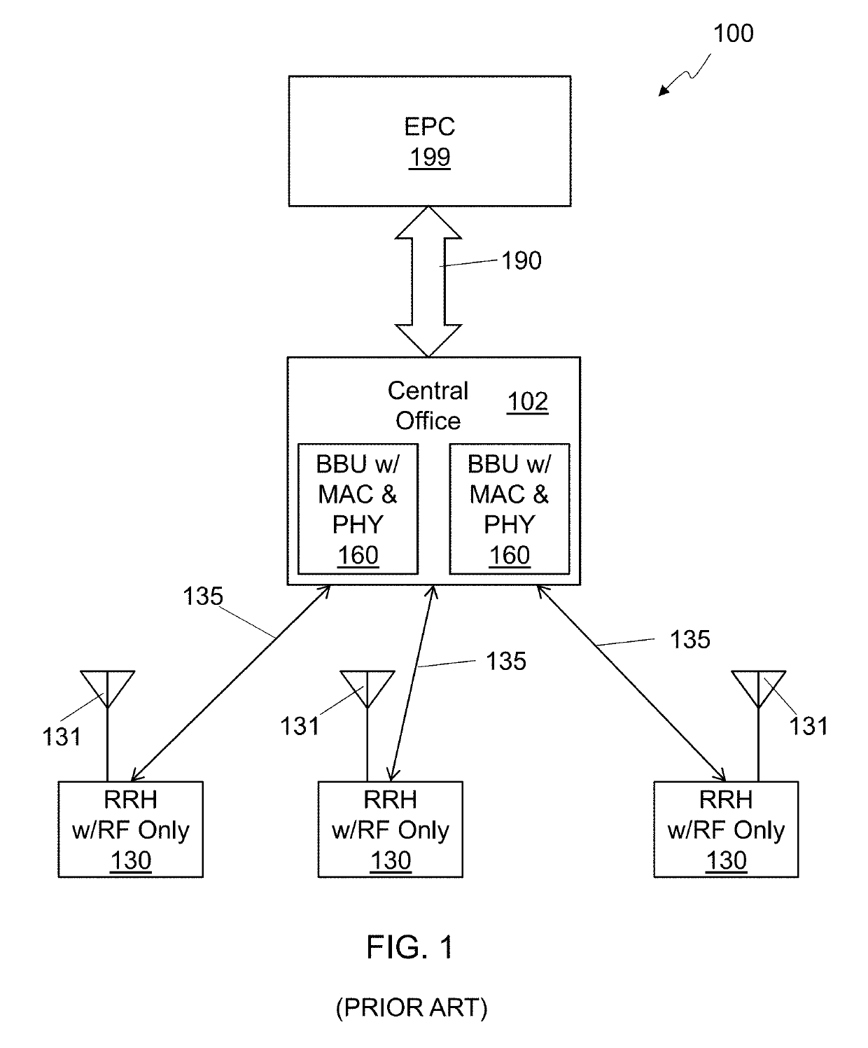
One key issue with a distributed RAN 100 architecture is latency.
If the overall latency for performing a specific function does not satisfy specific constraints imposed by the standard for the function, the system may fail, and communication between an eNB and a UE cannot be sustained.
Thus, latency constraints need to be satisfied in all operating conditions.
This requires hard, real-time, constraints on the processing of specific latency-constrained functions, or functions that have an impact on the overall system timeline.

Method used


Image

  • Management of a Split Physical Layer in a Radio Area Network
  • Management of a Split Physical Layer in a Radio Area Network
  • Management of a Split Physical Layer in a Radio Area Network

Examples


Embodiment Construction

[0025]In the following detailed description, numerous specific details are set forth by way of examples in order to provide a thorough understanding of the relevant teachings. However, it should be apparent to those skilled in the art that the present teachings may be practiced without such details. In other instances, well known methods, procedures and components have been described at a relatively high-level, without detail, in order to avoid unnecessarily obscuring aspects of the present concepts. A number of descriptive terms and phrases are used in describing the various embodiments of this disclosure. These descriptive terms and phrases are used to convey a generally agreed upon meaning to those skilled in the art unless a different definition is given in this specification. Some descriptive terms and phrases are presented in the following paragraphs for clarity.

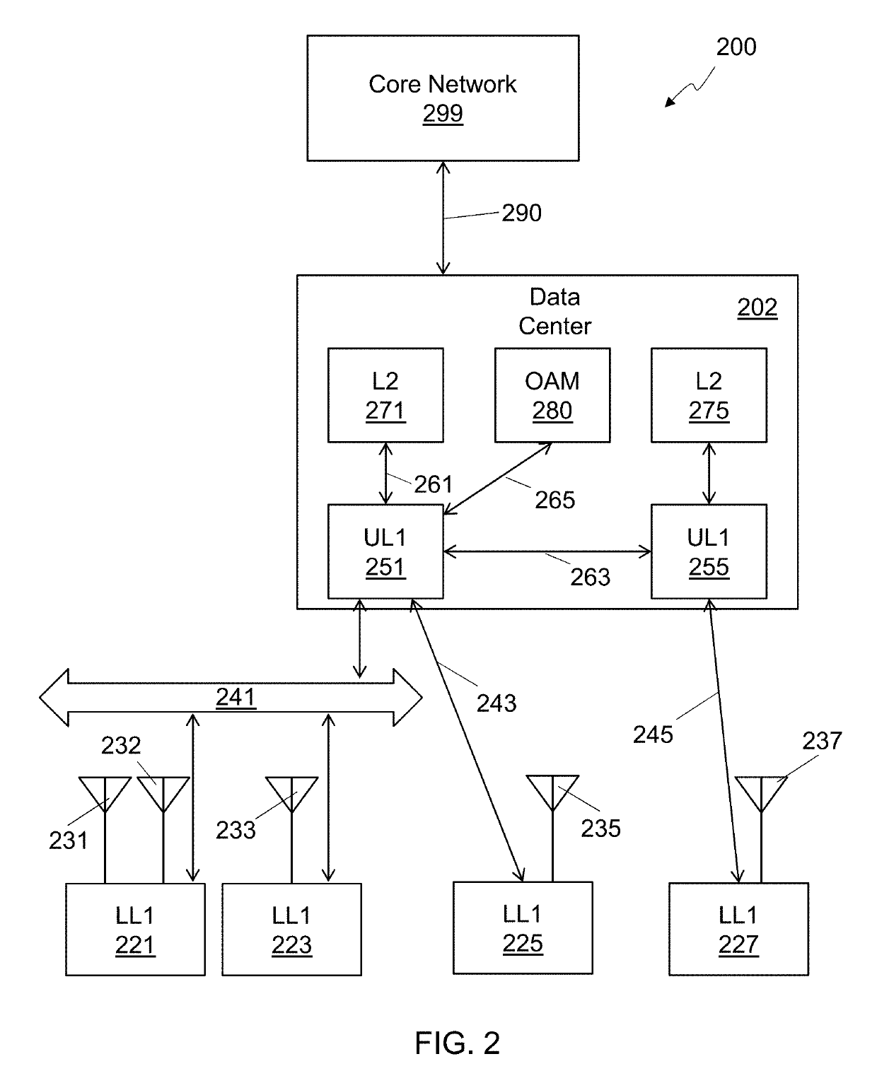
[0026]Lower first-level protocol unit (LL1), as the term is used herein, refers to a remote radio unit that includes...


PUM


Abstract

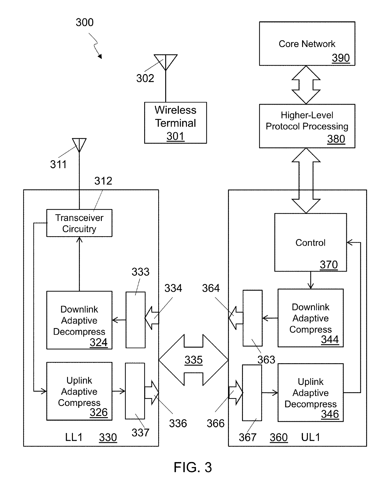
Methods and systems for facilitating communication between a core network and a wireless terminal in an upper first-level protocol unit (UL1) of a radio access network (RAN) as disclosed. An upper first level protocol unit (UL1) performs a first portion of a first-level protocol of the RAN in a first apparatus and communicates over a fronthaul link with a lower first-level protocol unit (LL1). The LL1 is in a second apparatus separate from the first apparatus. A communication quality parameter for communication between the first apparatus and the LL1 is determined, and a message related to the communication quality parameter is sent by the UL1 to an entity of the RAN other than the LL1.

Description

CROSS-REFERENCE TO RELATED APPLICATIONS[0001]This application claims the benefit of U.S. Provisional Application 62 / 613,665 entitled Methods for an Efficient Fronthaul Interface for Physical Layer Split Scenarios and filed Jan. 4, 2018. The aforementioned application is hereby incorporated by reference in its entirety herein for any and all purposes.BACKGROUNDTechnical Field[0002]The present subject matter relates to wireless communication. More specifically, the present subject matter relates to a radio access network (RAN) using an adaptive fronthaul protocol.Background Art[0003]A Radio Access Network (RAN) provides access to a core network for a wireless terminal, such as a smartphone. RANs have progressed through several different generations of technology, and are sometimes referred to by a so-called “generation number,” such as 3G, or 4G networks. An example 2G RAN is the GSM (Global System for Mobile Communications) Radio Access Network (GRAN), example 3G RANs include the GSM...

Claims


Application Information

Patent Timeline
Patent Type & Authority Applications(United States)
IPC IPC(8): H04W88/08H04W92/10H04W80/02H04W72/04
CPCH04W88/085H04W92/10H04W80/02H04W72/0446H04W28/18H04L1/0002H04L1/0014
Inventor BARBIERI, ALANFERTONANI, DARIO
Owner COMMSCOPE TECH LLC
Learn More