In-ear eeg device and brain-computer interfaces

a brain-computer interface and electrode-electronic technology, applied in the field of brain-computer interfaces and electroencephalogram devices, can solve the problems of long setup time, patient discomfort, and difficulty in reducing electrode impedances

Inactive Publication Date: 2019-07-11
HOLLAND BLOORVIEW KIDS REHABILITATION HOSPITAL
View PDF0 Cites 6 Cited by
  • Summary
  • Abstract
  • Description
  • Claims
  • Application Information

AI Technical Summary

Problems solved by technology

However, difficulty reducing electrode impedances, long setup times, patient discomfort,

Method used


Image

  • In-ear eeg device and brain-computer interfaces
  • In-ear eeg device and brain-computer interfaces
  • In-ear eeg device and brain-computer interfaces

Examples


Embodiment Construction

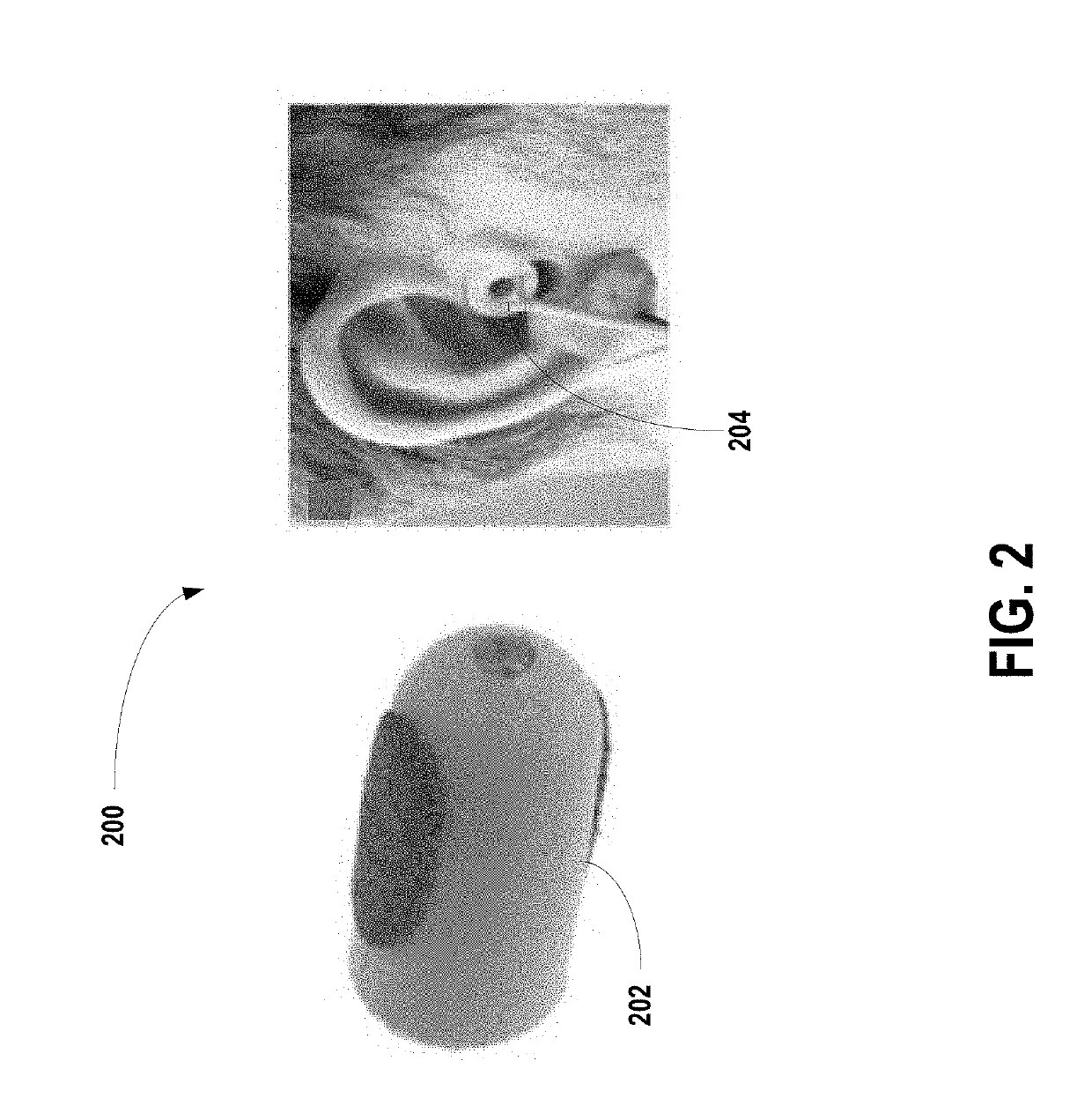
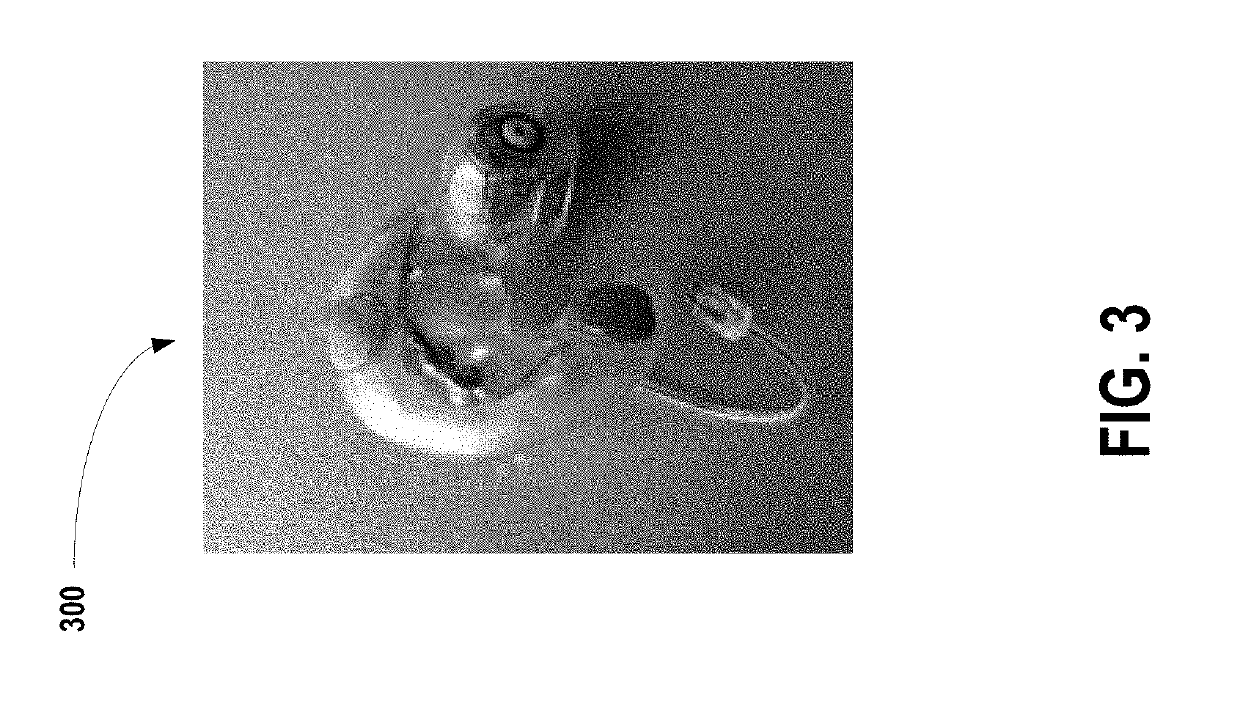
[0036]The present disclosure relates to in-ear EEG as a measurement system. Its small size provides improved user comfort, especially over long periods of time. The size and location also allows for improved discreetness. The location of the electrodes also provides robustness against eye-blink artifacts (though introduces greater susceptibility to artifacts related to facial muscle movements, i.e., mastication). There may be a limited number of electrodes, which precludes the use of EEG processing techniques such as independent component analysis (ICA). It is desirable to overcome the processing hurdles and relatively limited data.

[0037]Embodiments of methods, systems, and apparatus are described through reference to the drawings.

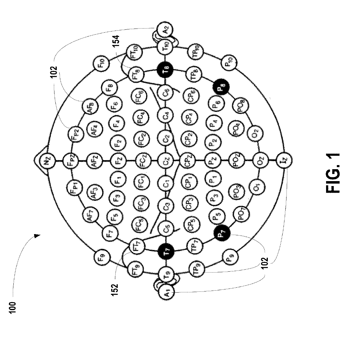
[0038]Some embodiments herein relate to in-ear electroencephalography (EEG) devices. The following terms are used in this disclosure:

[0039]ASSR: auditory steady-state response.

[0040]BCI: brain-computer interface.

[0041]CAD: computer-aided design.

[0042]CMRR:...


PUM


Abstract

An in-ear EEG device is provided. The in-ear EEG device comprises an over-ear support arm coupled to an enclosure, and an earpiece coupled to the enclosure. The enclosure has a power switch, an analog output, a power input, and a processor. The processor is configured to receive EEG data and generate output data for the analog output. The earpiece collects the EEG data and transmits the EEG data to the processor.

Description

FIELD[0001]The present disclosure generally relates to the field of brain-computer interfaces and electroencephalogram (EEG) devices.INTRODUCTION[0002]In-ear electroencephalography (EEG) is a method for measuring electrical signals from the brain. This technology is garnering increased interest in the research community and more broadly due to its advantages over conventional measurement systems. EEG caps, often used in brain-computer interface (BCI) systems and neuroscience research, present a non-invasive means to collect neural activity. However, difficulty reducing electrode impedances, long setup times, patient discomfort, and limited ability for long-term recording continue to plague EEG measurement systems.SUMMARY[0003]In accordance with one aspect, there is provided an in-ear electroencephalography (EEG) device. The EEG device comprises an enclosure, an earpiece coupled to the enclosure, and an over-ear support arm coupled to an enclosure. The enclosure has a power switch, a...

Claims


Application Information

Patent Timeline
IPC IPC(8): A61B5/0478A61B5/04A61B5/00A61B5/0484
CPCA61B5/0478A61B5/04012A61B5/6815A61B5/04845A61B5/7267A61B5/04842A61B5/048G06N20/00A61B5/0482G06N3/08G06N20/10A61B5/6817A61B5/316A61B5/375A61B5/38A61B5/378A61B5/291A61B5/374
Inventor SAAB, RAMICHAU, THOMAS TAK KIN
Owner HOLLAND BLOORVIEW KIDS REHABILITATION HOSPITAL
Why Eureka
Try Eureka