
Unmanned underwater vehicle and method for controlling hydraulic system

Active Publication Date: 2019-07-11
FUGRO
View PDF2 Cites 1 Cited by
  • Summary
  • Abstract
  • Description
  • Claims
  • Application Information

AI Technical Summary

Benefits of technology

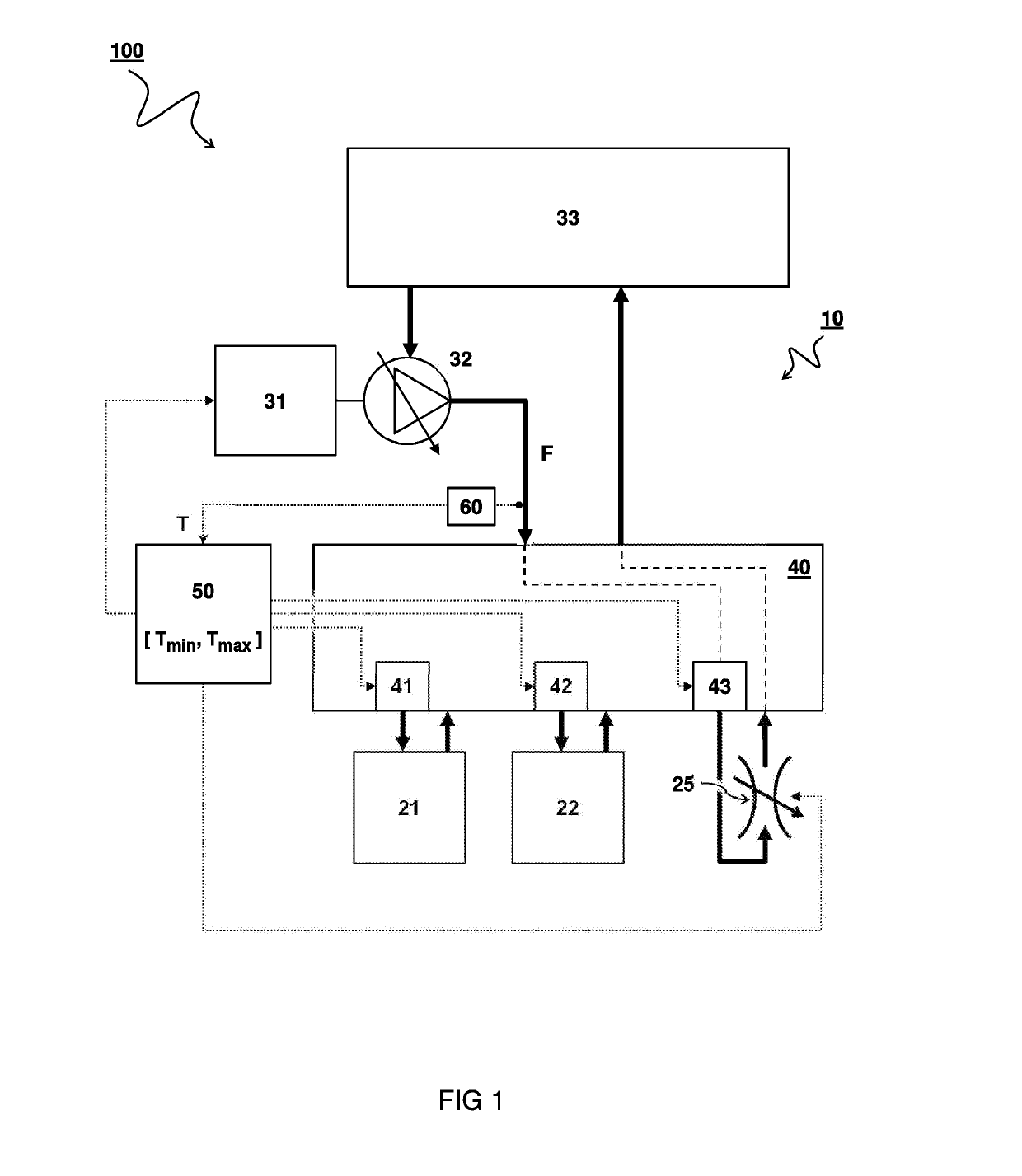
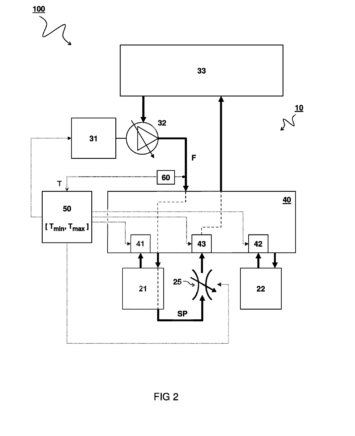
This patent is about controlling the flow of hydraulic fluid in a system using valves that are responsive to temperature. The system can activate or deactivate hydraulic fluid based on the temperature, preventing cooling of stagnant fluid. The control valves can also be used to control the flow of hydraulic fluid through separate circuits, without affecting the tools. The system can use a separate circuit for those tools that do not require activation, so as to maintain temperature. The amount of stagnant fluid in the system can be minimized by keeping a temperature control valve near the actuating control valve for the tools. This helps prevent the need for low viscosity oils and maintains the efficiency of the tools.

Problems solved by technology

However, when operating in deep water conditions, the hydraulic fluid may be affected by cold surroundings and / or high pressure of the water.
In particular, when the hydraulic fluid cools down, the fluid may become thick and difficult to move through the hydraulic circuit, especially if the fluid has become stagnant when a tool is not used for some time.
However, using low viscosity oil may affect operation at relatively high temperature conditions.
However, the heating mechanisms available underwater such as, e.g., electrical heating under water may consume too much power and could present failures, such as short circuits.
In this manner, the circulation of hydraulic fluid may in itself result in heating of the fluid, e.g. by friction and / or pump action.

Method used


Image

  • Unmanned underwater vehicle and method for controlling hydraulic system
  • Unmanned underwater vehicle and method for controlling hydraulic system

Examples


Embodiment Construction

[0019]In some instances, detailed descriptions of well-known devices and methods may be omitted so as not to obscure the description of the present systems and methods. Terminology used for describing particular embodiments is not intended to be limiting of the invention. As used herein, the singular forms “a”, “an” and “the” are intended to include the plural forms as well, unless the context clearly indicates otherwise. The term “and / or” includes any and all combinations of one or more of the associated listed items. It will be understood that the terms “comprises” and / or “comprising” specify the presence of stated features but do not preclude the presence or addition of one or more other features. It will be further understood that when a particular step of a method is referred to as subsequent to another step, it can directly follow said other step or one or more intermediate steps may be carried out before carrying out the particular step, unless specified otherwise. Likewise i...


PUM


Abstract

An unmanned underwater vehicle (UUV) with a hydraulic system (100) for use in cold surroundings and method of controlling such hydraulic system. The hydraulic system (100) comprises a hydraulic circuit (10). One or more tools (21,22) may be hydraulically operable via the hydraulic circuit (10). A pump (32) is configured to pressurize a flow of hydraulic fluid (F) via the hydraulic circuit (10) e.g. for actuating the tools (21,22). A valve system (40) comprises control valves (41,42,43) disposed in the hydraulic circuit (10) for controlling the flow of hydraulic fluid (F) through the hydraulic circuit (10). A controller (50) is configured to control one or more of the control valves (43) as a function of a temperature (T) of the hydraulic fluid (F).

Description

TECHNICAL FIELD AND BACKGROUND[0001]The present disclosure relates to an unmanned underwater vehicle for deep water conditions. The disclosure also relates to a method of controlling a hydraulic system in such a vehicle.[0002]A hydraulic system uses a pressurized hydraulic fluid, e.g. oil, to power hydraulic tools. The hydraulic system typically comprises a hydraulic pump driven by a motor to pressurize the hydraulic fluid. The pressurized fluid is guided via a hydraulic circuit to the tools. The hydraulic circuit may comprise valves, filters, piping etcetera to guide and control the system. A hydraulic tool may comprise an actuator such as a hydraulic motor or cylinder to actuate, i.e. mechanically drive, the machinery. Mechanical operation of the tools can be controlled e.g. by opening or closing hydraulic valves in the circuit between the pump and the tool.[0003]Hydraulic systems can be advantageously used under water because power can be conveniently transmitted without electric...

Claims


Application Information

Patent Timeline
IPC IPC(8): B63G8/00
CPCB63G8/001B63C11/52F15B21/042F15B2211/40515F15B2211/611F15B2211/6343B63G2008/002B63G8/00F15B2211/41563F15B2211/426F15B2211/62F15B2211/665F15B21/0427
Inventor ASH, BENJAMIN JEREMYANDERSON, ALAN NEILL
Owner FUGRO
Learn More