Vehicle control device and control method for vehicle

Active Publication Date: 2019-07-18
TOYOTA JIDOSHA KK
View PDF1 Cites 2 Cited by
  • Summary
  • Abstract
  • Description
  • Claims
  • Application Information

AI Technical Summary

Benefits of technology

The patent text describes a system that can correct the trajectory of a vehicle before another vehicle takes a curved path, which can make the ride less comfortable for the occupants. The system aims to make the ride more comfortable for the passengers.

Problems solved by technology

In such a case, the lane keeping assist system of the host vehicle detects that the adjacent preceding vehicle draws a curved path and corrects the target travel trajectory of the host vehicle; however, the target travel trajectory of the host vehicle cannot be corrected until the adjacent preceding vehicle travels along a curved path.
Consequently, occupants of the host vehicle may recognize that the target travel trajectory correction is delayed and feel uncomfortable.

Method used


Image

  • Vehicle control device and control method for vehicle
  • Vehicle control device and control method for vehicle
  • Vehicle control device and control method for vehicle

Examples


first embodiment

[0025]Constable Host Vehicle Margin & Variable Side-by-side Vehicle Margin

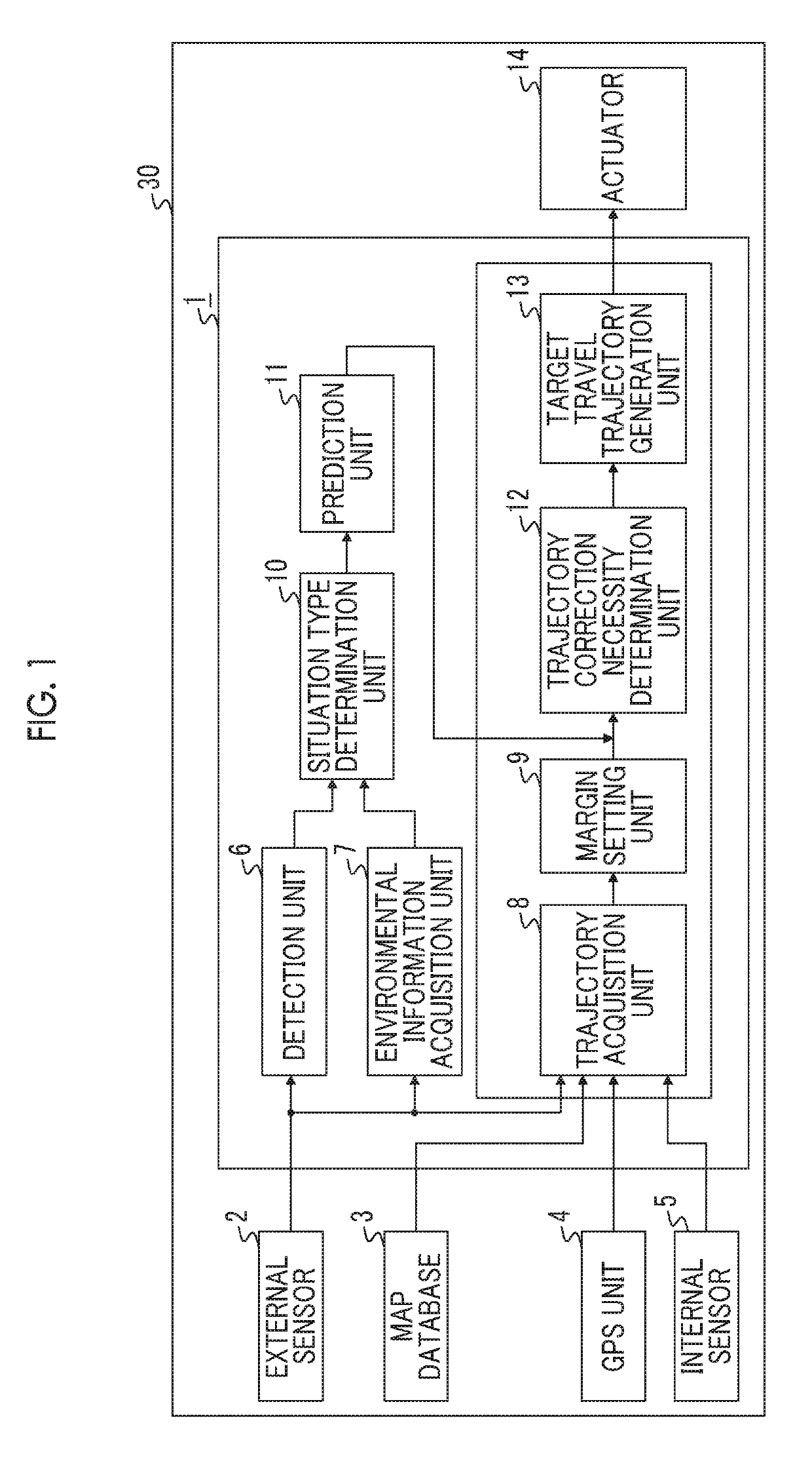
[0026]FIG. 1 is a block diagram illustrating a configuration of a host vehicle 30 in which a vehicle control device 1 of a first embodiment of the present disclosure is installed. The host vehicle 30 is provided with, as shown in FIG. 1, the vehicle control device 1, an external sensor 2 connected to the vehicle control device 1, a map database 3, a GPS unit 4, an internal sensor 5, and an actuator 14. The vehicle control device 1 is provided with a detection unit 6, an environmental information acquisition unit 7, a trajectory acquisition unit 8, a margin setting unit 9, a situation type determination unit 10, a prediction unit 11, a trajectory correction necessity determination unit 12, and a target travel trajectory generation unit 13, as a functional configuration.

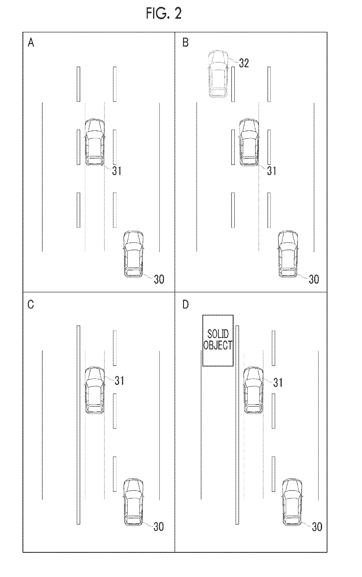
[0027]FIG. 2 shows a bird's-eye view illustrating four situation types including the host vehicle 30, an adjacent preceding vehicle 31 which tra...

second embodiment

[0079]Variable Side-by-side Zone

[0080]Next, a second embodiment will be described. Hereinafter, distinct features from the first embodiment will be described and repetitive descriptions will be omitted. A difference between the first embodiment and the second embodiment is that, in the second embodiment, the environmental information acquisition unit 7 variably sets a side-by-side zone. The following descriptions explain how to variably set a side-by-side zone by the environmental information acquisition unit 7.

[0081]The environmental information acquisition unit 7 of the second embodiment sets a length of the side-by-side zone in the traveling direction based on the velocity of the adjacent preceding vehicle 31. In the second embodiment, the length of the side-by-side zone in the traveling direction is set by multiplying the velocity of the adjacent preceding vehicle 31 by a specified number of seconds. That is, the length of the side-by-side zone in the traveling direction is a di...

third embodiment

[0084]Variable Adjacent Preceding Vehicle Travel Margin

[0085]Next, a third embodiment will be described. Hereinafter, distinct features from the first embodiment will be described and repetitive descriptions will be omitted. A difference between the first embodiment and the third embodiment is that, in the third embodiment, the prediction unit 11 obtains the predicted adjacent preceding vehicle lateral position based on a variable adjacent preceding vehicle travel margin. The following descriptions explain how to obtain the variable adjacent preceding vehicle travel margin used in the prediction unit 11.

[0086]FIG. 7 is a table illustrating correlations among the situation type shown in FIG. 2, the velocity of the adjacent preceding vehicle 31, which is an adjacent preceding vehicle, and the adjacent preceding vehicle travel margin. As shown in FIG. 7, the adjacent preceding vehicle travel margin proportionally increases as the velocity of the adjacent preceding vehicle increases. A ...


PUM


Abstract

A vehicle control device includes an external sensor configured to acquire environmental information around a host vehicle, and an electronic control unit. The electronic control unit is configured to control the host vehicle so that the host vehicle travels along a target travel trajectory; detect an adjacent preceding vehicle that is traveling in a lane adjacent to a lane in which the host vehicle is traveling; acquire environmental information on a road side or a lane on an opposite side of the lane in which the adjacent traveling vehicle is traveling from the lane in which the host vehicle is traveling; and generate the target travel trajectory of the host vehicle so as to move away from the adjacent preceding vehicle in a width direction of the lane in which the host vehicle is traveling, within a lane width of the lane in which the host vehicle is traveling.

Description

INCORPORATION BY REFERENCE[0001]The disclosure of Japanese Patent Application No. 2018-005924 filed on Jan. 17, 2018 including the specification, drawings and abstract is incorporated herein by reference in its entirety.BACKGROUND1. Technical Field[0002]The present disclosure relates to a vehicle control device and a control method for a vehicle.2. Description of Related Art[0003]Japanese Unexamined Patent Application Publication No. 2001-048036 (JP 2001-048036 A) discloses a lane keeping assist system for causing a host vehicle not to departure from a set target travel trajectory in which the target travel trajectory is corrected, based on detected off-lane obstacles which exist outside a lane of the host vehicle (host lane), by being shifted in a direction away from the off-lane obstacles when the host vehicle passes the off-lane obstacles. For example, when the host vehicle passes an adjacent preceding vehicle that is traveling in an adjacent lane, the target travel trajectory dr...

Claims


Application Information

Patent Timeline
IPC IPC(8): B62D6/00
CPCB62D6/001B62D6/002B60W30/12B62D15/025
Inventor OZAWA, JUNSATO, MINAMINAGATA, SHINICHI
Owner TOYOTA JIDOSHA KK
Why Eureka
Try Eureka