Transmission control device and transmission control method

a transmission control and transmission control technology, applied in the direction of gearing control, gearing element, belt/chain/gearring, etc., can solve the problems of increasing uncomfortable feeling and giving unintentional deceleration uncomfortable feeling to the driver of the vehicle, so as to reduce the uncomfortable feeling given at once by the control after failure and reduce the uncomfortable feeling due to the control after failure

Active Publication Date: 2018-03-08
JATCO LTD +1
View PDF0 Cites 0 Cited by
  • Summary
  • Abstract
  • Description
  • Claims
  • Application Information

AI Technical Summary

Benefits of technology

[0008]According to these aspects, in a case where the sub-transmission mechanism is shifted in accordance with the second control, the second control is executed at a different timing from the first control. Thus, uncomfortable feeling given at once by control after failure can be reduced. Therefore, uncomfortable feeling due to the control after the failure can be reduced.

Problems solved by technology

As a result, uncomfortable feeling is given to a driver of a vehicle by unintentional deceleration.
As a result, there is a concern that uncomfortable feeling is increased.

Method used


Image

  • Transmission control device and transmission control method
  • Transmission control device and transmission control method
  • Transmission control device and transmission control method

Examples


Embodiment Construction

[0018]Hereinafter, an embodiment of the present invention will be described with reference to the attached drawings.

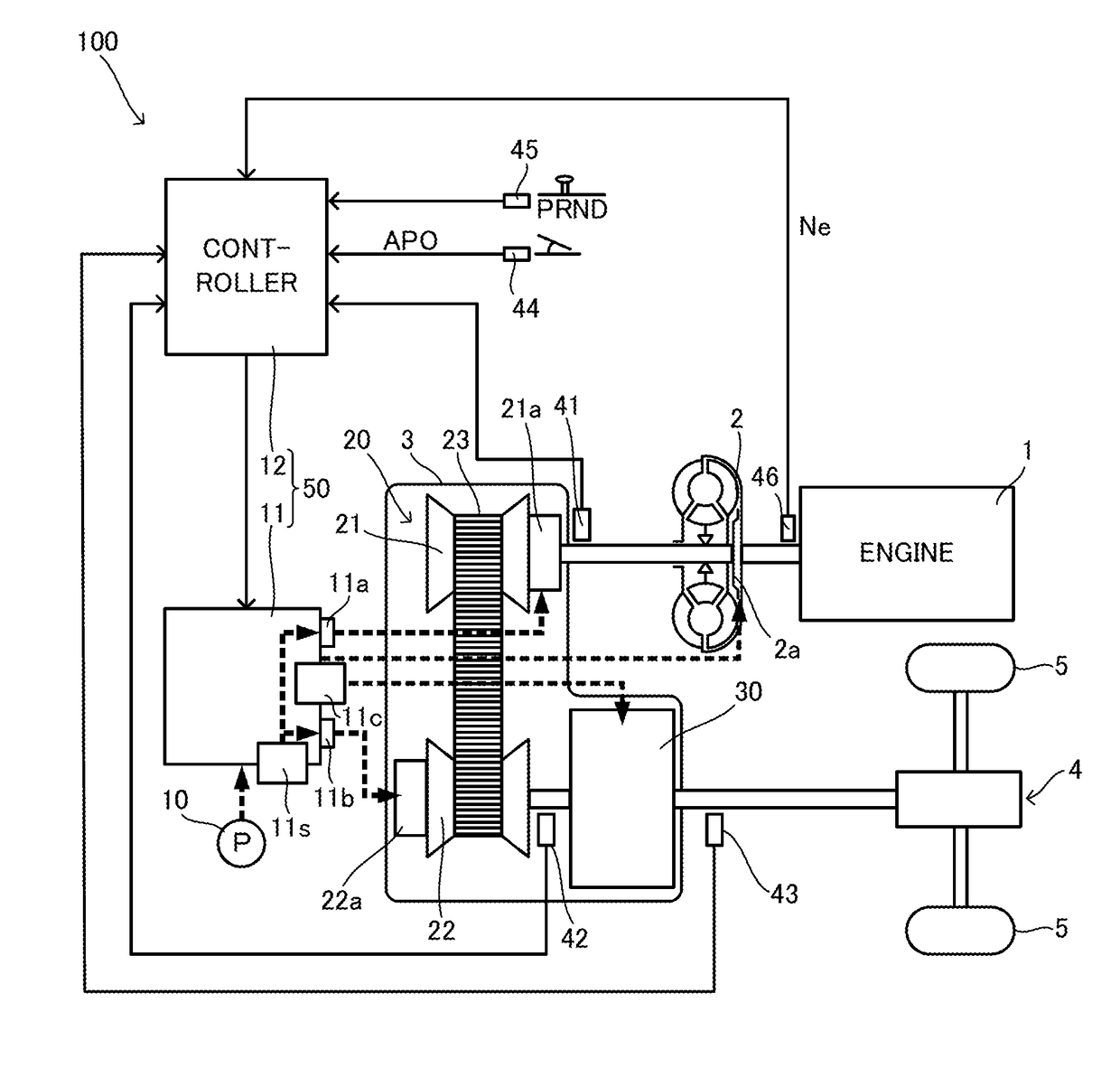
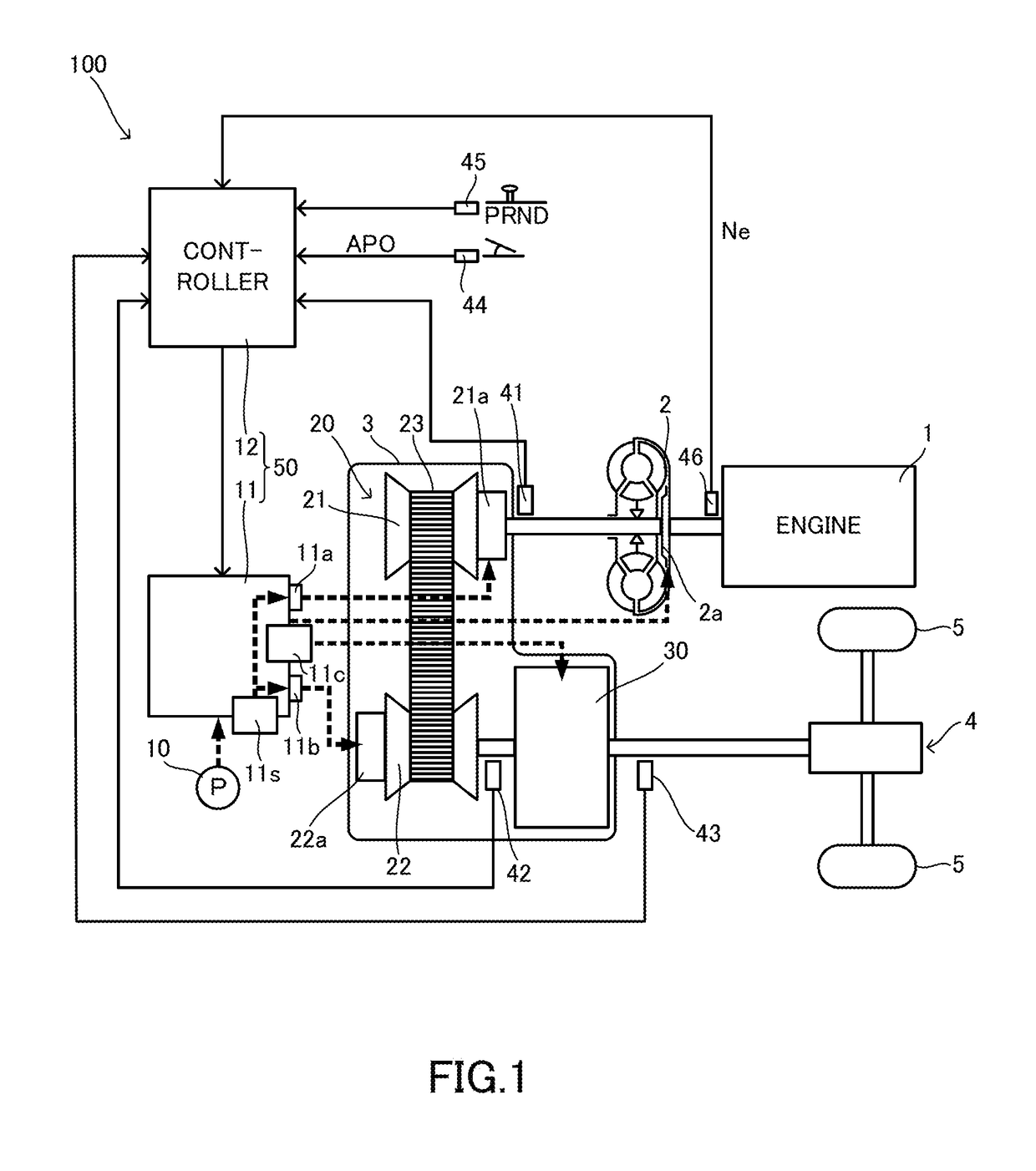
[0019]FIG. 1 is a diagram showing major portions of a vehicle including a transmission 100. The vehicle includes an engine 1, a torque converter 2, a variator 20, a sub-transmission mechanism 30, an axle 4, and drive wheels 5.

[0020]The engine 1 forms a power source of the vehicle. The torque converter 2 transmits power via a fluid. In the torque converter 2, by engaging a lock-up clutch 2a, power transmission efficiency can be enhanced. The variator 20 and the sub-transmission mechanism 30 output inputted rotation speed as rotation speed in accordance with a speed ratio. The speed ratio has a value obtained by dividing the inputted rotation speed by the outputted rotation speed. The axle 4 is a drive axle formed by a reduction gear and a differential device. The power of the engine 1 is transmitted to the drive wheels 5 via the torque converter 2, the variator 20, the ...


PUM


Abstract

In a transmission control device, a controller determines failure of a rotation sensor. A hydraulic control circuit and the controller variably control a speed ratio of a variator, and in a case where the failure is determined, execute first control of restricting a shift range of the variator. The hydraulic control circuit and the controller variably control a gear position of a sub-transmission mechanism, and in a case where the failure is determined, execute second control of fixing the gear position of the sub-transmission mechanism to first speed. The hydraulic control circuit and the controller execute the second control at a different timing from the first control in a case where the gear position of the sub-transmission mechanism upon a determination of the failure is second speed.

Description

TECHNICAL FIELD[0001]The present invention relates to a transmission control device and a transmission control method.BACKGROUND ART[0002]A technique of performing a fail-safe at the time of failure of a rotation speed sensor of a secondary pulley in a continuously variable transmission is disclosed in JP5-46465B. In this technique, at the time of the failure of the rotation speed sensor of the secondary pulley, a speed ratio is fixed to the maximum speed ratio, that is, the lowest speed ratio.SUMMARY OF INVENTION[0003]In the technique of JP5-46465B, even in a case where a speed ratio of a variator having a primary pulley, a secondary pulley, and a belt is, for example, the minimum speed ratio, that is, the highest speed ratio immediately before failure, the speed ratio is fixed to the lowest speed ratio immediately after the failure. As a result, uncomfortable feeling is given to a driver of a vehicle by unintentional deceleration.[0004]In such a way, due to a fail-safe, not a litt...

Claims


Application Information

Patent Timeline
Patent Type & Authority Applications(United States)
IPC IPC(8): F16H61/12F16H59/40F16H63/50
CPCF16H61/12F16H59/40F16H63/502F16H61/662F16H2061/6614F16H61/702F16H2061/1232F16H2061/1244F16H2061/1284B60W2710/1088B60W10/107B60W10/11B60W2710/1005B60W2710/1083
Inventor OZONO, HARUKAHAMANO, MASAHIRO
Owner JATCO LTD
Why Eureka
Try Eureka