
Voice signal decoding device and voice signal decoding method

a voice signal and decoding device technology, applied in the field of voice signal decoding device and voice signal decoding method, can solve the problems of inability to perform codecs and practicably inconvenient, and achieve the effect of suppressing an auditory uncomfortable feeling

Active Publication Date: 2020-05-14
PANASONIC INTELLECTUAL PROPERTY MANAGEMENT CO LTD
View PDF0 Cites 0 Cited by
  • Summary
  • Abstract
  • Description
  • Claims
  • Application Information

AI Technical Summary

Benefits of technology

The patent describes a device and method that can reduce the discomfort experienced when listening to music or speech during codec switching. This improves the overall quality of the audio experience.

Problems solved by technology

When the switching of the codecs is performed in the silence period as in PTL 1, the switching of the codecs cannot be performed until it becomes the silence period, which is practically inconvenient.

Method used


Image

  • Voice signal decoding device and voice signal decoding method
  • Voice signal decoding device and voice signal decoding method
  • Voice signal decoding device and voice signal decoding method

Examples


Embodiment Construction

[0015]Exemplary embodiments of the present disclosure will be described in detail below with reference to the drawings.

(1) Principle

[0016]First, a principle of the present exemplary embodiment will be described.

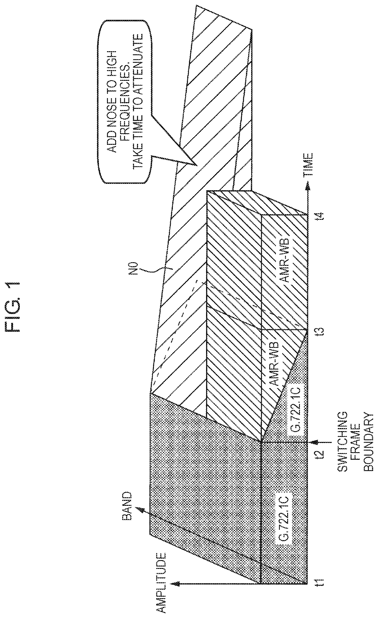
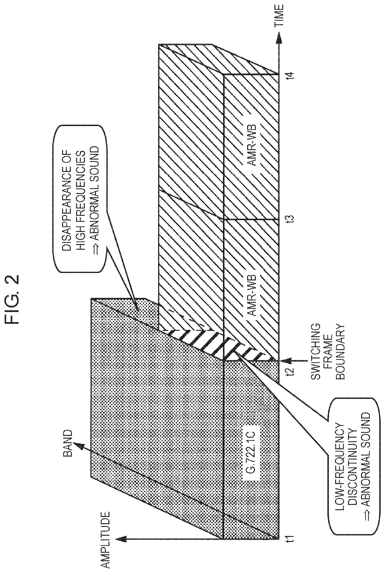
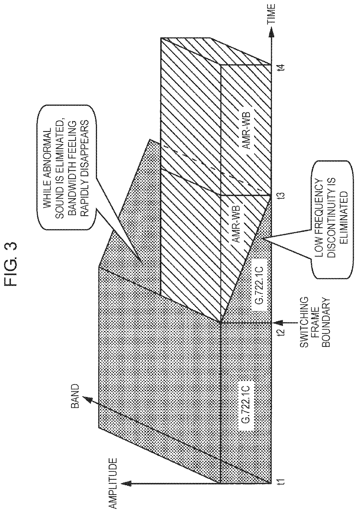
[0017]FIG. 1 is a diagram showing the principle of a decoding method according to the exemplary embodiment. In FIG. 1, the principle when the switching is performed from a first codec using a first encoding method to a second codec using a second encoding method is shown. As the first codec, a codec conforming with G.722.1C is used. As the second codec, a codec conforming with AMR-WB is used. As evident from the figure, the first codec (G.722.1C) has a band wider than the second codec (AMR-WB).

[0018]When the first codec and the second codec are compared, the second codec lacks a signal component in a high-frequency band. In the decoding method of the present exemplary embodiment, noise signal NO gradually attenuating with time from a time point t2 when the codec is switched f...


PUM


Abstract

A voice signal decoding device includes a first decoder, a second decoder, a signal switch, and a noise adder. The first decoder decodes first encoded data encoded by a first encoding method. The second decoder decodes second encoded data encoded by a second encoding method. The second encoded data has a narrower band than a band of the first encoded data. The signal switch switches an output signal of t first decoder and an output signal of the second decoder. The noise adder adds a noise signal to a high-frequency band in the output signal of t second decoder when the signal switch switches an output signal from the output signal of the first decoder to the output signal of the second decoder. The high-frequency band is a band where a signal component is lacking as compared with the output signal of the first decoder.

Description

TECHNICAL FIELD[0001]The present disclosure relates to a voice signal decoding device and a voice signal decoding method used in a dual codec voice transmission system using different codecs.BACKGROUND ART[0002]Conventionally, there has been a voice transmission system in which codecs in use are switched in accordance with a state of a transmission line or the like. In such a voice transmission system, for example, when a wide-band codec can be used, the wide-band codec is used, and when the wide-band codec cannot be used, a narrow-band codec is used.[0003]When the codecs are switched, noise and the like occurring at the time of switching need to be reduced to suppress an auditory uncomfortable feeling. As one method therefor. Patent Literature 1 discloses a technique of switching encoding means (codecs) in a silence period to prevent the occurrence of the noise accompanying the switching of the encoding means (the codecs).CITATION LISTPatent LiteraturePTL 1: Unexamined Japanese Pat...

Claims


Application Information

Patent Timeline
Patent Type & Authority Applications(United States)
IPC IPC(8): G10L19/028G10L19/22
CPCG10L19/028G10L19/22G10L19/24G10L21/038H03M7/30
Inventor EHARA, HIROYUKIKAWASHIMA, TAKUYA
Owner PANASONIC INTELLECTUAL PROPERTY MANAGEMENT CO LTD
Learn More