Electricity generation control device for vehicle

a technology for electric power generation and control devices, which is applied in vehicle position/course/altitude control, process and machine control, instruments, etc., can solve the problems of inability to permit electricity generation, and inability to control electricity generation. , to achieve the effect of suppressing uncomfortable feelings, rapid change of engine rotation speed, and superior virtual electricity generation efficiency

Active Publication Date: 2013-04-02
MITSUBISHI ELECTRIC CORP
View PDF11 Cites 0 Cited by
  • Summary
  • Abstract
  • Description
  • Claims
  • Application Information

AI Technical Summary

Benefits of technology

[0013]In addition, another object of the invention is to suppress an adverse effect on drivability such as a rapid change in an engine rotation speed or the like, which is caused by a rapid change in a control state, by gradually approaching the state where the relation between the fuel amount, which increases accompanied with the electricity generation, and the electricity generation amount.
[0016]According to the electricity generation control device of the first aspect of the invention, the virtual electricity generation efficiency is calculated at the time of virtually changing at least one of the transmission gear ratio of the continuously variable transmission, the electricity generation drive torque and the engine drive torque with a minute amount from the present state, and the minute amount changing process is repeatedly performed, in a case where the virtual electricity generation efficiency is superior to the present electricity generation efficiency, such that it is possible to gradually approach a control state where the electricity generation efficiency becomes best. In addition, according to the electricity generation device of the first aspect, at least one of the transmission gear ratio of the continuously variable transmission, the electricity generation drive torque and the engine drive torque is gradually changed, such that it is possible to suppress uncomfortable feeling such as a rapid change in the engine rotation speed caused by the rapid change in the control state.
[0017]According to an electricity generation control device of the second aspect of the invention, at least one of the transmission gear ratio of the continuously variable transmission, the electricity generation drive torque and the engine drive torque is actually changed with a minute amount, the electricity generation efficiency is calculated from the fuel consumption amount and the electricity generation amount that are detected, and a process of returning at least one of the transmission gear ratio of the continuously variable transmission, the electricity generation drive torque and the engine drive torque to a state before changing with a minute amount is repeatedly performed in a case where the calculated electricity generation efficiency is inferior to the electricity generation efficiency calculated before changing with a minute amount at least one of the transmission gear ratio of the continuously variable transmission, the electricity generation drive torque and the engine drive torque. Therefore, it is possible to gradually reach a control state where the electricity efficiency becomes best. In addition, according to an electricity generation control device of the second aspect of the invention, when it is compared with the electricity generation control device of the first aspect, since a fuel injection amount and the electricity generation amount may be calculated without referring a table, it is not necessary to perform a complicated process. In addition, since the actual fuel injection amount and actual electricity generation amount are detected and then the control is performed, it is not affected by an error effect caused by environmental factor such as a production tolerance, a temporal change or the like.

Problems solved by technology

However, in a case where the power is insufficient while driving, the electricity generator is driven by an engine to generate electricity for the insufficient power.
Therefore, in the device of the related art disclosed in JP-A-2010-125877, when the electricity generation by the engine drive while driving is performed, it may be impossible to control the electricity generation so as to be performed in a state where the engine efficiency becomes best.
In addition, since characteristics of an electricity generator are not considered, the electricity generation is frequently performed in a state where a relation between the fuel amount, which increases accompanied with the electricity generation, and the electricity generation amount is not best.
However, in a case contrary to this, the electricity generation is not permitted.
However, in the above-described control, since the engine rotation speed is not changed, it may be impossible to generate electricity in a point where the engine efficiency becomes best.
As described above, in the device of the related art disclosed in JP-A-2010-125877, since a transmission gear ratio is not controlled at the time of generating electricity and the electricity generation state is determined by only the engine efficiency without considering the characteristics of the electricity generator, it may be impossible to generate electricity at a state where the electricity generation efficiency becomes best.

Method used


Image

  • Electricity generation control device for vehicle
  • Electricity generation control device for vehicle
  • Electricity generation control device for vehicle

Examples


embodiment 1

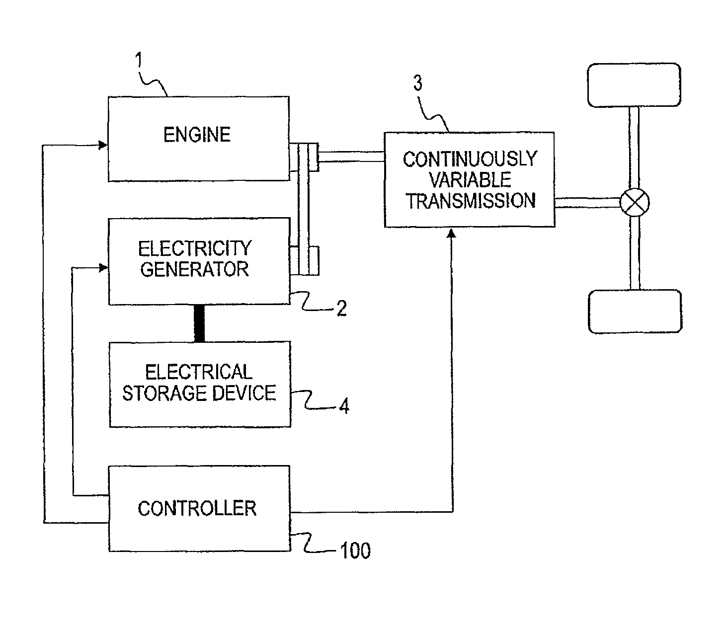
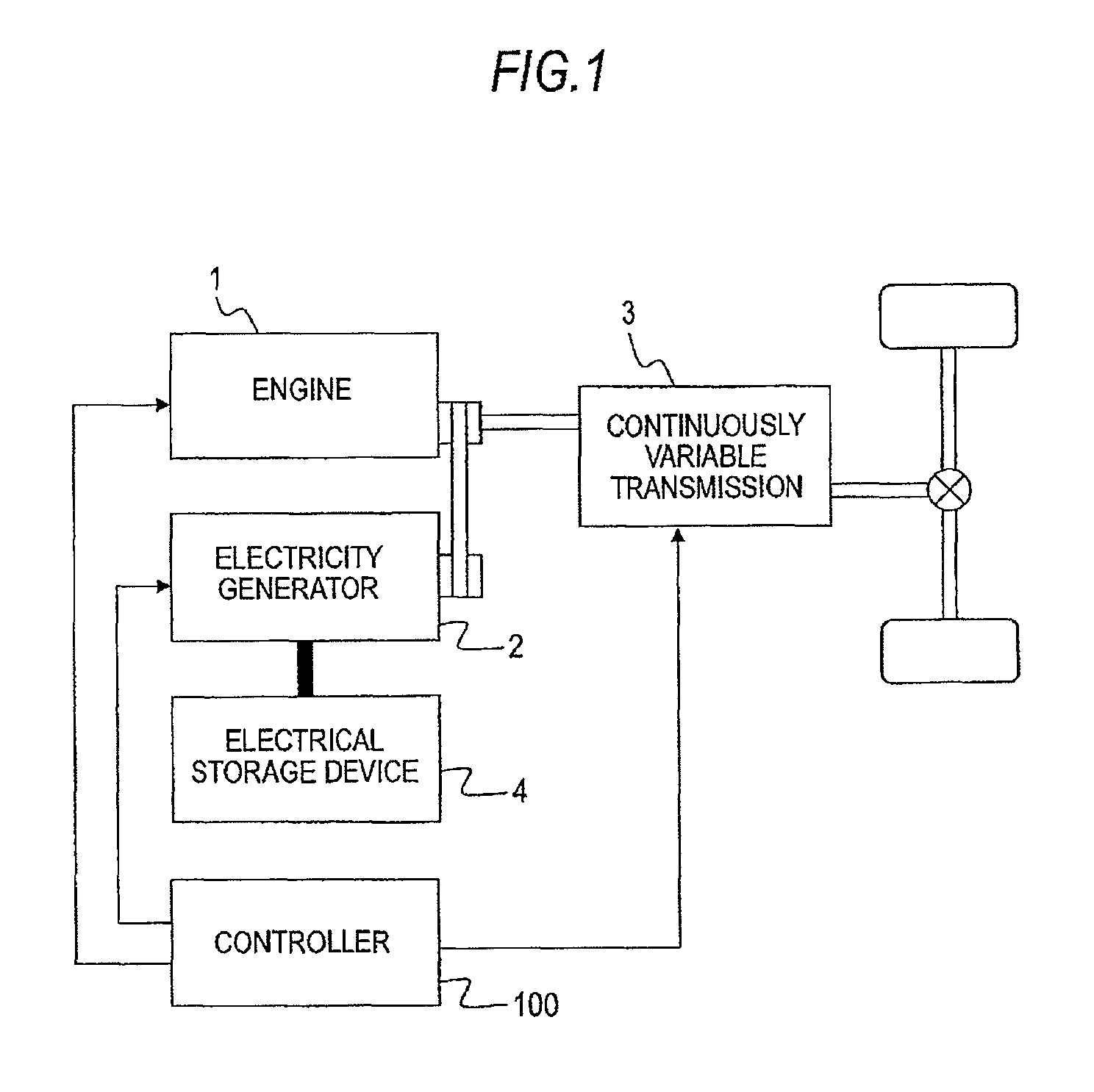
[0038]FIG. 1 shows a configuration diagram illustrating an electricity generation control device according to an embodiment 1 of the invention.

[0039]In FIG. 1, a connection is made to transmit the power of an engine 1, which is a power source of a vehicle, to a continuously variable transmission (CVT) 3. The continuously variable transmission 3 changes the speed of the power of an engine 1 to transmit the power to drive wheels of the vehicle. A transmission gear ratio of the continuously variable transmission 3 may varies as a continuous value. An electricity generator 2 connects to the engine 1 to followingly-rotate and generates electricity by the power of the engine 1 to supply the power to an electrical storage device 4 such as a battery. A controller 100 controls an engine drive torque of the engine 1, detects an engine rotation speed thereof, controls an electricity generation drive torque of the electricity generator 2, detects an electricity generator rotation speed, and con...

embodiment 2

[0070]In the embodiment 1, the electricity generation efficiency in a case where the engine drive torque or the transmission gear ratio is virtually changed is calculated, and an operation for actually changing the engine drive torque or the transmission gear ratio is repeatedly performed in a case where the calculated virtual electricity generation efficiency is superior to the present electricity generation efficiency. Contrary to this, in the embodiment 2, the engine drive torque or the transmission gear ratio is actually changed, the electricity generation efficiencies before and after the change are compared with each other, and then an operation for returning into the engine drive torque or the transmission gear ratio before the change is repeatedly performed in a case where the electricity generation efficiency before the change is superior to that after the change.

[0071]FIG. 8 shows a configuration diagram of an electricity generation control device according to the embodime...

embodiment 3

[0086]In the embodiment 2, the electricity generation efficiency in a case where the control point is changed with a minute amount from a point of time when the electricity generation is needed is compared with that before changing the control point, and the process for changing the control point is performed in a case where the electricity generation efficiency after the change is superior to that before the change. In the embodiment 3, at a point of time when the electricity generation is needed, an electricity generation drive torque increases to secure a minimum electricity generation amount, and then a process for changing the control point is performed. For example, the minimum value is set to an amount of power that is being discharged by an electrical storage device in no electricity generation state or the like.

[0087]Next, the transition of each of the transmission gear ratio, the electricity generation drive torque and the electricity generation efficiency in a case of per...


PUM


Abstract

An electricity generation control device calculates a virtual electricity generation efficiency where a transmission gear ratio of a continuously variable transmission is changed with a minute amount when an electricity generation condition by an engine drive is realized, changes the transmission gear ratio with a minute amount in a case where the virtual electricity generation efficiency is superior to a present electricity generation efficiency, calculates a virtual electricity generation efficiency where an engine drive torque and an electricity generation drive torque are changed with a minute amount, and changes the engine drive torque and the electricity generation drive torque in a case where the virtual electricity generation efficiency is superior to a present electricity generation efficiency, in which the minute amount change of the transmission gear ratio and the minute amount change of the engine drive torque and the electricity generation drive torque are alternatively performed.

Description

BACKGROUND OF THE INVENTION[0001]1. Field of the Invention[0002]The present invention relates to an electricity generation control technology in a vehicle including an electricity generator and a continuously variable transmission.[0003]2. Background Art[0004]Recently, an electricity generation control system of which an electricity generation amount of an electricity generator which rotates following an output shaft of an engine is variable to efficiently perform an electricity generation has been developed. In general, the electricity generation control system increases an electricity generation amount during deceleration of the vehicle to recover the kinetic energy of the vehicle as a power. However, in a case where the power is insufficient while driving, the electricity generator is driven by an engine to generate electricity for the insufficient power.[0005]There has been suggested a technology that does not permit the electricity generation by the engine in a case where an en...

Claims


Application Information

Patent Timeline
Patent Type & Authority Patents(United States)
IPC IPC(8): B60L9/00
CPCB60W10/06B60W10/101B60W10/30B60W30/1882B60W30/1886B60W10/08B60W20/102B60W2510/0638B60W2510/0657B60W2510/1005B60W2520/10Y02T10/6286B60W20/11Y02T10/62
Inventor HAYASHI, KENSUKEWACHI, SATOSHIKAMIOKA, NOZOMU
Owner MITSUBISHI ELECTRIC CORP
Why Eureka
Try Eureka