A frame for an implantable medical device and a method of manufacturing a frame for an implantable medical device

a medical device and implantable technology, applied in the field of frames for implantable medical devices, can solve the problems of increasing the chance of dislodging calcified plaques in the native valve, difficult valve positioning,

Active Publication Date: 2019-07-25
UNIV OF SOUTHAMPTON +1
View PDF0 Cites 18 Cited by
  • Summary
  • Abstract
  • Description
  • Claims
  • Application Information

AI Technical Summary

Benefits of technology

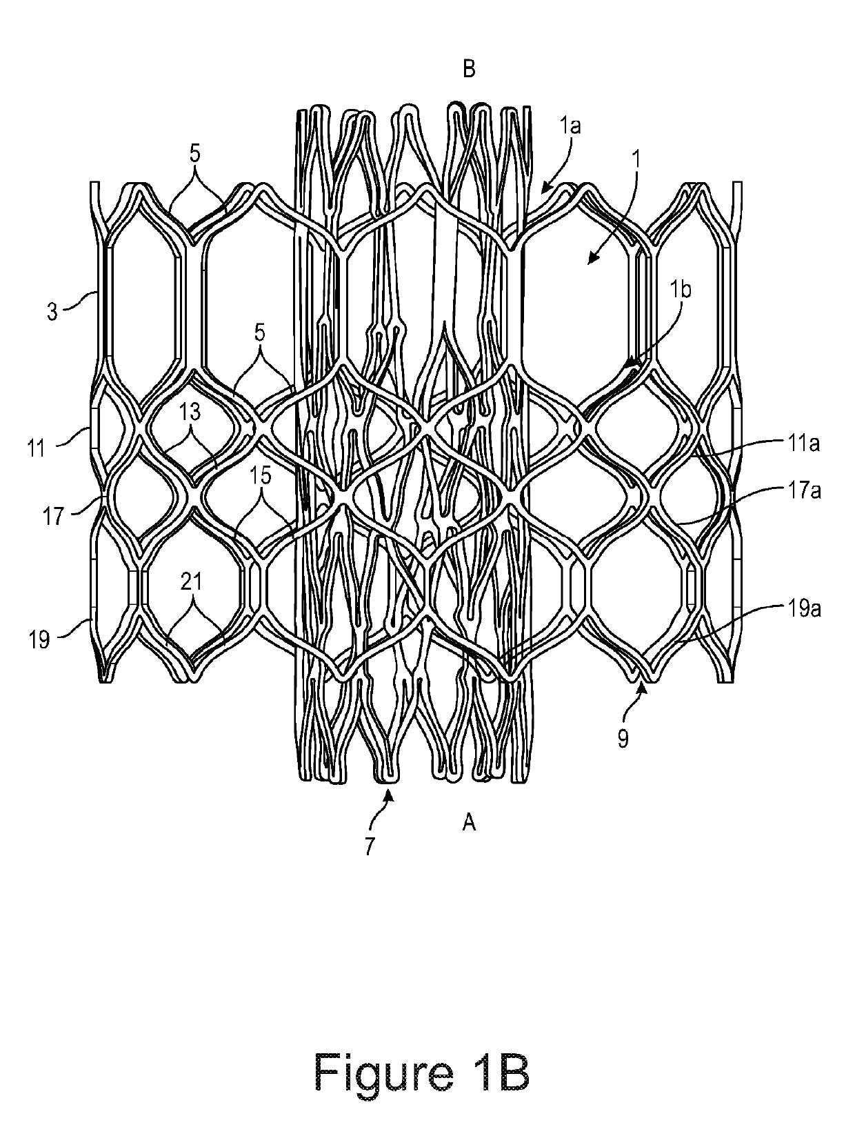
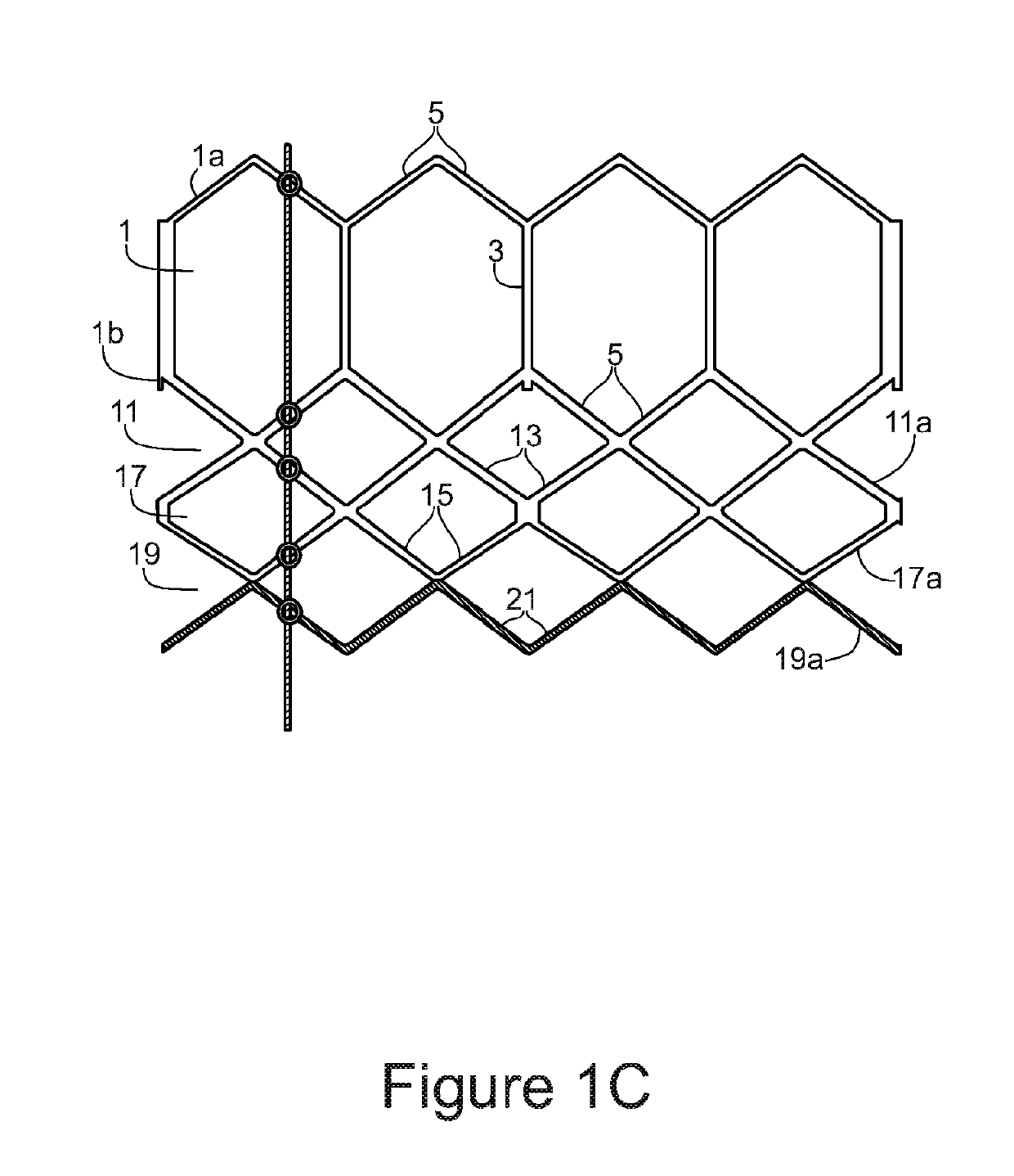
[0039]In an embodiment, the second member comprises one or more rings of cells, each of which are connected to other rings of cells only through struts which do not have a component in the circumferential direction. The second member may be located at a middle portion of the frame.
[0040]In a further embodiment, the first member comprises one or more rings of cells, each of which are connected to other rings of cells only through struts which do not have a component in the circumferential direction.
[0041]In an embodiment, the change in length of the first member between the radially contracted state and the radially expanded state is more than the change in length of the second member between the radially contracted state and the radially expanded state.
[0042]In an embodiment, the first member comprises more vertices connected between three or more struts extending in a direction which has a component in the circumferential direction than the second member.

Problems solved by technology

This is referred to as foreshortening, and can make valve positioning more difficult and increase the chance of dislodging calcified plaques in the native valve.

Method used


Image

  • A frame for an implantable medical device and a method of manufacturing a frame for an implantable medical device
  • A frame for an implantable medical device and a method of manufacturing a frame for an implantable medical device
  • A frame for an implantable medical device and a method of manufacturing a frame for an implantable medical device

Examples


first embodiment

[0112]FIG. 2(a) is a schematic illustration of a frame for an implantable medical device in accordance with the present invention. The frame may be for an implantable heart valve device for example. FIG. 2(b) shows the frame in an unwrapped illustration. The unwrapped illustration corresponds to the frame if it was cut along one side in the longitudinal direction, such that it is unrolled to form a rectangle. FIG. 2(c) shows the frame in a radially expanded state and a radially contracted state.

[0113]The frame comprises a first end A and a second end B. In an embodiment, the frame is a cylindrical shape.

[0114]The frame is a multi-layered frame. The frame comprises a first member 201, which corresponds to a first layer, comprising a plurality of struts defining a plurality of cells and a second member 202, which corresponds to a second layer, comprising a plurality of struts. The cells are the spaces enclosed by the struts.

[0115]In an embodiment, the first member defines more cells t...

fifth embodiment

[0227]FIG. 8 is a schematic illustration of a frame for an implantable medical device in accordance with the present invention. The frame may be for an implantable heart valve device for example. FIG. 9(a) shows an illustration of the frame in an unwrapped configuration.

[0228]The frame of FIG. 8 comprises a plurality of rings of cells, connected through struts extending in the longitudinal direction, with no component in the circumferential direction. The cells are not connected through vertices between three or more struts extending in a direction which has a component in the circumferential direction only. In other words, the rings are connected by struts which do not have a component in the circumferential direction. The change in length of each of the rings is thus independent.

[0229]The frame comprises a first member 201 and a second member 202. The first member 201 comprises three rings of cells and the second member 202 comprises one ring of cells.

[0230]The frame comprises a f...

seventh embodiment

[0327]FIG. 15 is a schematic illustration of a frame for an implantable medical device in accordance with the present invention. The frame may be for an implantable heart valve device for example. FIG. 16(a) shows the frame in a radially expanded state and FIG. 16(b) shows the frame in a radially contracted state.

[0328]The frame comprises a first end A and a second end B. In an embodiment, the frame is a cylindrical shape.

[0329]The frame is a multi-layered frame. The frame comprises a first member 201, which corresponds to a first layer, comprising a plurality of struts defining a plurality of cells and a second member 202, which corresponds to a second layer, comprising a plurality of struts. In this embodiment, the second member 202 does not define any cells.

[0330]The first member 201 is annular and defines a longitudinal direction which is parallel to the axis of the first member, a radial direction, and a circumferential direction. The first member 201 and the second member 202 ...


PUM


Abstract

A frame for an implantable medical device, comprising: a first member, comprising a plurality of struts defining a plurality of cells, wherein the first member is annular and defines a longitudinal direction which is parallel to the axis of the first member, a radial direction, and a circumferential direction; a second member, comprising a plurality of struts and coupled to the first member at circumferentially distributed locations; wherein the second member overlaps a first end portion of the first member and extends beyond the first end portion of the first member.

Description

FIELD[0001]The present invention relations to frames for implantable medical devices and methods of manufacturing such frames.BACKGROUND[0002]Implantable medical devices include devices such as stents and valves. These devices are implanted into a patient and it is usually intended that they remain implanted in the patient permanently. Such implantable medical devices may comprise a frame which provides the structure of the device.[0003]Transcatheter implantation methods have been developed, particularly for the aortic valve. A conventional implantable device for a heart valve comprises a metal frame, a skirt, which may be stitched to the frame, and a set of three leaflets, which may be stitched to the skirt and secured to the commissures of the frame. The metal frame comprises a plurality of struts defining a plurality of cells and may be cylindrical. This type of device may be crimped on a balloon catheter so that it can moved into position percutaneously before being opened throu...

Claims


Application Information

Patent Timeline
Patent Type & Authority Applications(United States)
IPC IPC(8): A61F2/24A61F2/852
CPCA61F2/2418A61F2/2415A61F2/852A61F2210/0076A61F2220/0058A61F2220/0075A61F2250/0007A61F2250/0018A61F2250/0039A61F2250/0063
Inventor BRESSLOFF, NEIL W.BAILEY, JONATHAN
Owner UNIV OF SOUTHAMPTON
Why Eureka
Try Eureka