Connector assembly connecting cables for power transmission

Active Publication Date: 2019-07-25
KYUNG CHANG IND
View PDF0 Cites 0 Cited by
  • Summary
  • Abstract
  • Description
  • Claims
  • Application Information

AI Technical Summary

Benefits of technology

The invention includes a fastening portion with a protruding portion that allows for easy pressing. This makes it easier to securely attach parts together.

Problems solved by technology

This connector device has a structure incapable of obtaining a free stroke between the cables and it is troublesome to use tools when separating the cables.

Method used


Image

  • Connector assembly connecting cables for power transmission
  • Connector assembly connecting cables for power transmission
  • Connector assembly connecting cables for power transmission

Examples


Embodiment Construction

[0032]Embodiments of the present disclosure will be described in more detail with reference to the accompanying drawings. In the components of the present disclosure, detailed descriptions of what can be clearly understood and easily carried into practice through prior art by those skilled in the art will be omitted to avoid making the subject matter of the present invention unclear.

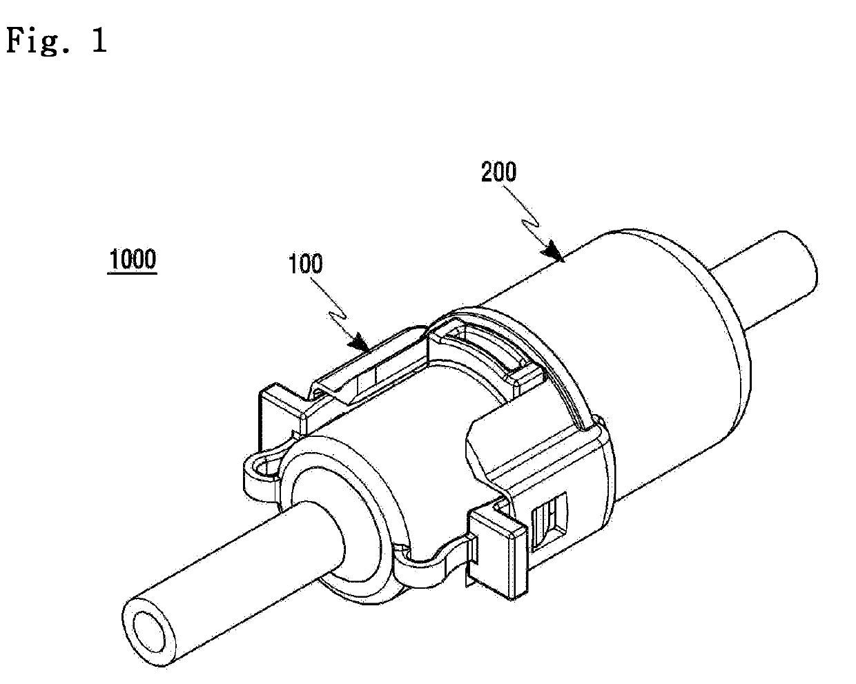
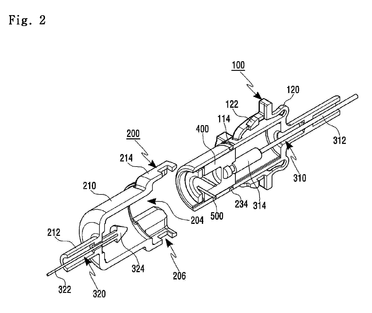
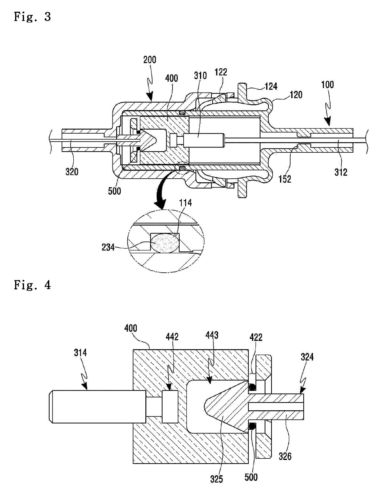
[0033]FIG. 1 is a view showing a connector assembly according to an embodiment of the present disclosure. FIG. 2 is a sectional perspective view of the connector assembly in which a first socket member and a second socket member have been separated from each other according to an embodiment of the present disclosure. FIG. 3 is a sectional front view of the connector assembly in which the first socket member and the second socket member have been connected to each other according to an embodiment of the present disclosure.

[0034]Referring to FIG. 1 and FIG. 2, a connector assembly 1000 connects cables for ...


PUM


Abstract

A connector assembly connecting cables for power transmission may be provided. The connector assembly includes: a first linking body connected to one cable; a second linking body connected to another cable; a coupling member which is coupled to the first linking body and the second linking body and includes a catching groove formed on one end thereof and a catching opening formed along a circumference of the other end thereof; and a spring which includes two L-shaped rods and a bridge connecting the L-shaped rods, the bridge being coupled to the catching groove when the spring is mounted on the coupling member, the two L-shaped rods being coupled to the catching opening.

Description

CROSS-REFERENCE TO RELATED APPLICATIONS[0001]This application claims the benefit of Republic of Korea Patent Application No. 10-2018-0007244 filed on Jan. 19, 2018, which is incorporated by reference in its entirety.BACKGROUNDField[0002]The present disclosure relates to a device for transmitting the power in mechanisms such as a vehicle, etc.Description of the Related Art[0003]In general, many types of cables or members are mounted on mechanisms such as a vehicle, etc. The cables or members which are used in mechanisms are connected and transmit the power.[0004]For example, a gear shift is performed by operating a shift lever arranged on the driver's seat. The cable is mainly used as a connection member which transmits the power according to the operation of the shift lever to the transmission.[0005]A connector device is employed to connect these cables. The power is transmitted through the connector device. A conventional connector device uses a method of fixing the cables and has ...

Claims


Application Information

Patent Timeline
IPC IPC(8): H01R13/627
CPCH01R13/6275H01R13/6273F16C1/14F16C1/145H01R13/20H01R2201/26H01R13/635H01R13/633
Inventor LEE, CHANG MINLEE, DAE WONKIM, KYUNG NAM
Owner KYUNG CHANG IND
Why Eureka
Try Eureka