
Systems and methods for pre-operative visualization of a joint

Active Publication Date: 2019-08-01
STRYKER CORP
View PDF0 Cites 5 Cited by
  • Summary
  • Abstract
  • Description
  • Claims
  • Application Information

AI Technical Summary

Benefits of technology

The patent text describes a system and method for helping a physician plan a surgical procedure to address joint pathologies, such as hip joint disorders. The system uses pre-operative joint visualization to help the physician understand the extent of the pathology and decide how much bone needs to be removed during the procedure. The system analyzes image data of the joint and generates a virtual 3D model of the joint. The model includes a visual indication of the region of the joint that deviates from the baseline anatomy, and the system can also provide information on the bone and the position of the bone in relation to the joint. The method can help improve the accuracy of the surgical procedure and minimize damage to the joint.

Problems solved by technology

Joint injuries or conditions such as those of the hip joint or other joints can occur from overuse or over stretching or due to other factors, including genetic factors, and may cause deviation from the baseline anatomy of the joint.
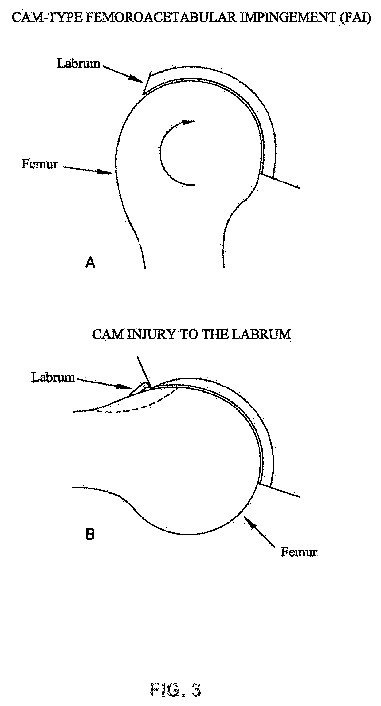
FAI can result in a reduced range of motion, substantial pain and, in some cases, significant deterioration of the hip joint.
In some cases, the FAI may be sufficiently severe as to require surgical intervention, e.g., removal of the bone causing the FAI and repair of any damaged soft tissues.
However, when treating FAI using minimally-invasive arthroscopic techniques, it is generally quite difficult for the physician to determine exactly how much bone should be removed, and whether the shape of the remaining bone has a desired geometry.
In practice, physicians tend to err on the side of caution and remove less bone rather than more bone.
Significantly, under-resection of the pathology is the leading cause of revision hip arthroscopy.
A Lateral Center Edge Angle of between 20-25 degrees is typically indicative of borderline undercoverage and may result in hip instability, a Lateral Center Edge Angle of less than 20 degrees is typically indicative of hip dysplasia, and a Lateral Center Edge Angle of greater than 40 degrees is typically indicative of overcoverage (pincer-type FAI) and may result in hip impingement and a decreased range of motion.
Acetabular version of 15-20 degrees is generally considered normal, while acetabular anteversion greater than 25 degrees is considered indicative of anterior undercoverage and may result in hip instability.
Acetabular retroversion (i.e.: acetabular version less than 15 degrees) can be indicative of posterior superior undercoverage or anterior overcoverage and may result in hip instability, or hip impingement, or both.
Femoral torsion of 10-20 degrees is considered normal, while femoral torsion of greater than 25 degrees is considered pathologic and may result in hip instability.
Femoral torsion of less than 5 degrees is considered pathologic and may result in hip impingement.

Method used


Image

  • Systems and methods for pre-operative visualization of a joint
  • Systems and methods for pre-operative visualization of a joint
  • Systems and methods for pre-operative visualization of a joint

Examples


Embodiment Construction

[0100]Reference will now be made in detail to implementations and embodiments of various aspects and variations of the invention, examples of which are illustrated in the accompanying drawings. Various devices, systems, and methods are described herein. Although at least two variations of the devices, systems, and methods are described, other variations may include aspects of the devices, systems, and methods described herein combined in any suitable manner having combinations of all or some of the aspects described. Example embodiments will now be described more fully hereinafter with reference to the accompanying drawings; however, they may be embodied in different forms and should not be construed as limited to the embodiments set forth herein. Rather, these embodiments are provided so that this disclosure will be thorough and complete, and will fully convey exemplary implementations to those skilled in the art.

[0101]According to some embodiments, systems and methods according to...


PUM


Abstract

A method for visualizing at least one region of a joint that deviates from a baseline anatomy includes receiving image data associated with a joint of a subject, generating a three-dimensional model of at least a portion of the joint using the image data, identifying at least one region of the joint that deviates from the baseline anatomy by comparing the three-dimensional model to a baseline model, generating a measurement of a characteristic of the joint at one or more predefined locations using the three-dimensional model and a coordinate system, and generating a three-dimensional rendering of the model that includes a visual indication of the at least one region of the three-dimensional model that deviates from the baseline so that the region is visually indicated according to degree of deviation, and a representation of the measurement of the characteristic of the joint that is positioned according to the predefined locations.

Description

CROSS-REFERENCE TO RELATED APPLICATIONS[0001]This patent application claims benefit of pending prior U.S. Provisional Patent Application Ser. No. 62 / 623,068, titled HIPMAP™ FEMOROACETABULAR IMPINGEMENT ANALYSIS FAI and filed Jan. 29, 2018, the entire contents of which are hereby incorporated herein by reference.FIELD OF THE INVENTION[0002]This invention generally relates to orthopedics, and more particularly to pre-operative planning for orthopedic procedures.BACKGROUND OF THE INVENTION[0003]Orthopedics is a medical specialty that focuses on the diagnosis, correction, prevention, and treatment of patients with skeletal conditions, including for example conditions or disorders of the bones, joints, muscles, ligaments, tendons, nerves and skin, which make up the musculoskeletal system. Joint injuries or conditions such as those of the hip joint or other joints can occur from overuse or over stretching or due to other factors, including genetic factors, and may cause deviation from the...

Claims


Application Information

Patent Timeline
IPC IPC(8): A61B34/10A61F2/30G06F17/50
CPCA61B34/10A61F2/30942G06F17/50A61B2034/105A61B2034/102A61B2017/564A61B34/25G06F30/00
Inventor LAMBERS, FLOORKAISER, WILLIAM
Owner STRYKER CORP
Learn More