A system and a method for determining a trajectory to be followed by an agricultural work vehicle

a technology for agricultural work and a system, applied in the direction of vehicle position/course/altitude control, process and machine control, instruments, etc., can solve the problems of excessive time consumption, weight gain, and weight loss in the working operation

Active Publication Date: 2019-08-08
AGRO INTELLIGENCE APS
View PDF0 Cites 34 Cited by
  • Summary
  • Abstract
  • Description
  • Claims
  • Application Information

AI Technical Summary

Benefits of technology

[0017]ii) coordinates relating to the boundaries of one or more obstacles to be avoided by said work vehicle; wherein said one or more obstacles being located within said field;
[0018]a capacity parameter unit configured for receiving one or more capacity parameters relating to said working vehicle;
[0019]a trajectory calculating unit configured for calculating an optimized trajectory to be followed by said work vehicle; wherein said optimized trajectory is being calculated on the basis of said coordinates received by said mapping unit; and one or more of said one or more capacity parameters received by said capacity parameter unit.

Problems solved by technology

Furthermore, as various types of working implement for working a field will typically have different efficient working widths or other working parameters, it may not be the case that an optimum working path in respect of one working implement will be optimum in respect of another implement involving different working parameters.
Some agricultural working implement gain weight during operation, whereas others lose weight during operation thereof.
When working farm land in a non-optimized way in which the trajectory which is followed is not an optimum trajectory, excessive time consumption in the working operation, excessive fuel consumption, excessive areas of the field covered more than once, and excessive wear on the working implement or machinery, or excessive travelling through the crops may result

Method used


Image

  • A system and a method for determining a trajectory to be followed by an agricultural work vehicle
  • A system and a method for determining a trajectory to be followed by an agricultural work vehicle
  • A system and a method for determining a trajectory to be followed by an agricultural work vehicle

Examples


example 1

[0154]The following example discloses in detail one way of performing the mathematical operations necessary in the process of going from a field boundary to creating possible individual candidate trajectories and the step of assigning an efficiency parameter to each of those candidate trajectories so that the most efficient candidate trajectory can be chosen as the optimum trajectory when working that field with an agricultural working vehicle or implement.

[0155]The present example is based on the principle involving the following steps:[0156]a) approximating the coordinates relating to the boundaries of said field to be worked to a boundary polygon;[0157]b) approximating the coordinates relating to the boundaries of each said one or more obstacles, to respective obstacle polygons;[0158]c) defining one or more headlands located immediately within said boundary polygon;[0159]d) in respect of each obstacle polygon, defining one or more headlands surrounding said obstacle polygon;[0160...

example 2

[0287]This example illustrates the present invention. This example illustrates in an very simplified and idealized way how the invention is to be conducted.

[0288]In this example an agricultural field comprising a number of obstacles needs to be worked by an agricultural working vehicle or implement.

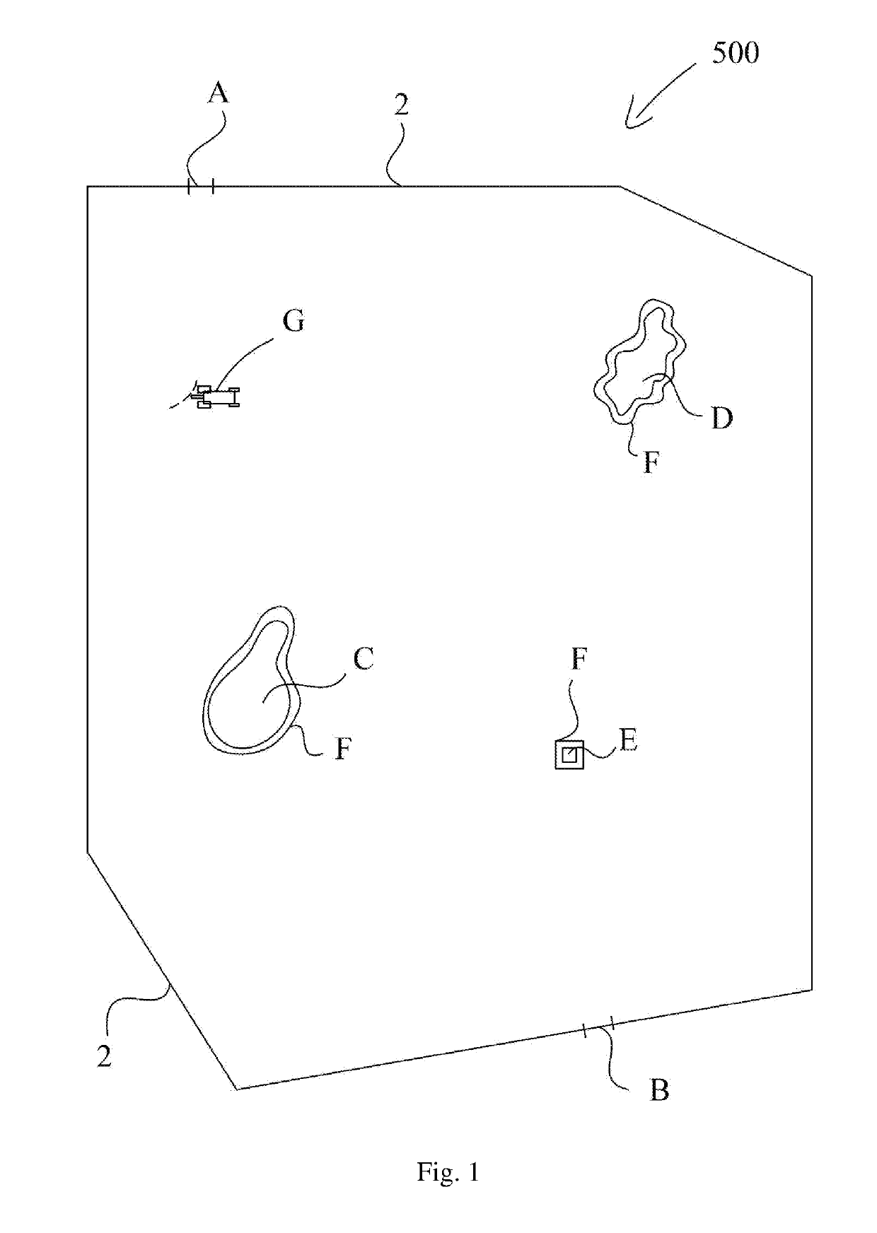
[0289]FIG. 24 illustrates the field to worked. The field 500 is constrained within a field boundary 2. At a specific location on the field boundary 2 an entrance / exit gate is located.

[0290]The field boundary comprises two pairs of parallel lines. In the lower right corner of the field shown in FIG. 24 two perpendicular boundary lines are connected by a circular path.

[0291]Within the field boundary 2 two obstacles 8, which obviously must be avoided when working the field, are located.

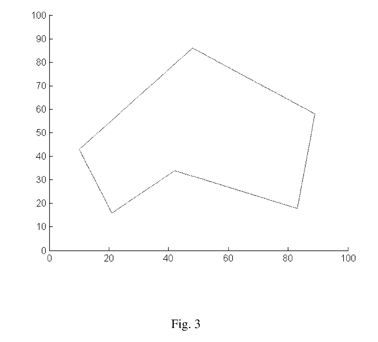
[0292]First, the field boundary 2 is approximated to the shape of a polygon. This is illustrated in FIG. 25.

[0293]FIG. 25 shows that the boundary 2 of FIG. 24 has been approximated to a polygon. This polygon i...


PUM


Abstract

The present invention relates to a support system for determining a trajectory to be followed by an agricultural work vehicle, when working a field, said system comprises:
  • a mapping unit configured for receiving:
    • i) coordinates relating to the boundaries of a field to be worked; and
    • ii) coordinates relating to the boundaries of one or more obstacles to be avoided by said work vehicle; wherein said one or more obstacles being located within said field;
  • a capacity parameter unit configured for receiving one or more capacity parameters relating to said working vehicle;
  • a trajectory calculating unit configured for calculating an optimized trajectory to be followed by said work vehicle; wherein said optimized trajectory is being calculated on the basis of said coordinates received by said mapping unit; and one or more of said one or more capacity parameters received by said capacity parameter unit.

Description

FIELD OF THE INVENTION[0001]The present invention generally relates to the field of optimizing work trajectories of agricultural working vehicles for working a field. More specifically the present invention relates in a first aspect to a support system for determining a trajectory to be followed by an agricultural work vehicle when working a field. In a second aspect the present invention relates to a method for optimizing a trajectory to be followed by a work vehicle when working a field. In a third aspect the present invention relates to a computer program product which is adapted to perform the method according to the second aspect of the present invention. In a fourth aspect the present invention relates to an agricultural work vehicle comprising a support system according to the first aspect of the present invention. In a fifth aspect the present invention relates to a use of a support system according to the first aspect of the present invention, or of a computer program produ...

Claims


Application Information

Patent Timeline
Patent Type & Authority Applications(United States)
IPC IPC(8): A01B79/00G01C21/20G05D1/02A01B69/04
CPCA01B79/005G01C21/20G05D1/0219A01B69/008G05D2201/0201A01B69/007
Inventor GREEN, OLEEDWARDS, GARETH THOMAS CHARLES
Owner AGRO INTELLIGENCE APS
Why Eureka
Try Eureka